


48
Connectors, Plugs and Cables
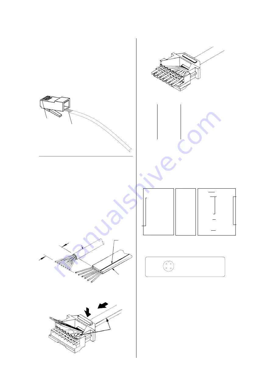
3. Use the diagrams below for proper
matching of color- to-contact:
76
5 4
3
8
2
1
white lead to
nr. 1
2. Insert cable into lid and fix it there.
Standard version: RJ45 plug
Bus cable
Contact Nr.1
white lead
"Western" Plug
-- For Alternate Bus version (8 lead)
-- For Compass Sensor (8 lead)
-- For NMEA in-/out (8 lead)
-- For Log Sensor (6 lead)
-- For Wind Sensor (6 lead)
-- For Heading Gyro (6 lead)
Plug Installation:
1. Remove the cable's jacket.
~15 mm
Round
cable
Flat
cable
white
lead
Bus cable: 8-pin plug, 4-wire cable
Pin
round
flat
#
cable
cable
1
white
white
2
brown
blue
3
yellow
cyan
4
green
magenta
5,6,7 and 8 must remain unconnected
Wind & Compass Sensor and Echo-Box:
8-pin plug:
Flux Gate
Echobox
PB100 Wind-
HS8000
-1 or -2
Sensor
RJ45 round
flat
6-lead
4-lead
pin# cable
cable
cable
cable
1
red (white)
white
red
white
2
green (brwn) blue
black
brown
3
cyan
(jmpr 2-
4 (jumper 2-7
magenta
7 inside
5
inside RJ45)
white
orange RJ45)
6
blue (yello.) orange
yellow
yellow
7
brown
blue
8
yellow (grn.)
red
white
green
Note: leads 3 and 4 are the CAN-bus sig-
nals. They must not be connected to a sensor
or to the Echo-Box.
Log and Wind Sensor, Sonic Heading
Gyro, Roll and Pitch Angle Sensor, Mast
Angle Sensor:
6 pin plug, 4-wire cable:
pin
round
flat-oval
#
cable
cable
2
white
white
3
brown
blue
4
yellow
cyan
5
green
magenta
pin 1 and 6 must remain unconnected
The white lead of the four lead flat cable
goes to the left side of the plug (contact nr. 1)
and the remaining leads are placed to the
adjacent contacts 2,3,4.
Contacts 5,6,7,8 must re-
main free. Attention must
be paid to the situation of
the plug as depicted,
to avoid inter-
changing
contacts 1
and 8.
yellow
red
green
blue
HS8000: Sensor
Cable Connector, as
seen from the cable
side
1
2
4
3
RJ45
pin#
1
2
3
4
5
6
7
8


