146
Chapter 12—Common Channel Functions
DM2000 Version 2—Owner’s Manual
3
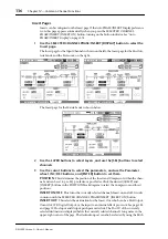
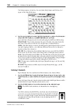
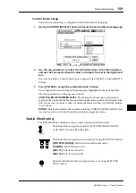
Use the cursor buttons or Parameter wheel to select the channel pair but-
tons, and press [ENTER] to make or break pairs.
Input and Output Channels can also be selected by using the LAYER and [SEL] buttons.
A dialog box appears with options for copying the settings of the first channel to the second
channel, the second channel to the first channel, and for resetting both channels to their ini-
tial settings. Choose the option required, and then press [ENTER].
On other display pages, paired channels have a heart icon, or a dash between their channel
numbers.
When Input Channels are paired, MS Decoding can be used to decode signals from micro-
phones arranged as MS pairs. MS Decoding is set on the Input Channel Pair pages. This can
be turned on and off for each pair of channels by using the MS buttons.
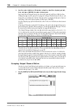
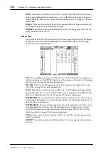
The Output Pair page displays the currently selected Surround mode (i.e., Stereo, 3-1, 5.1,
or 6.1), which can be set on the Surround Mode page (see page 97). When a Surround mode
other than Stereo is selected, the names of the Surround channels are shown below the Bus
Out and Aux Send pair buttons, as shown in the following table.
This table shows the default assignment. The assignment may vary depending on the set-
tings in the Surround Bus Setup page (see page 99).
When a Surround mode other than Stereo is selected, Aux Sends can be set to follow the
same Input Channel Surround Pan that applies to the Bus Outs, which is useful for feeding
Surround channel signals to external effects processors. This is turned on and off by using
the F.S buttons that appear below the Aux Send Pair buttons. When a pair of Aux Sends are
set to follow Surround Pan, their Aux Send Pair button is unavailable, and their Aux Pan
parameters (see page 116) are unavailable.
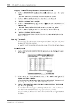
Grouping Output Channel Faders
The Bus Out, Aux Send, Matrix Send, and Stereo Out faders can be grouped, allowing you
to control the level of several Output Channels simultaneously. There are four Output
Channel Fader groups: Q, R, S, and T.
1
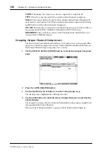
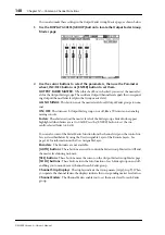
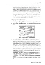
Use the DISPLAY ACCESS [GROUP] button to locate the Output Fader Group
page.
Surround Mode
Bus Out/Aux Send
1
2
3
4
5
6
7
8
3-1
L
R
C
S
—
—
—
—
5.1
L
R
Ls
Rs
C
LFE
—
—
6.1
L
R
Ls
Rs
C
Bs
LFE
—

