140
Chapter 12—Common Channel Functions
DM2000 Version 2—Owner’s Manual
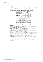
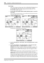
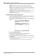
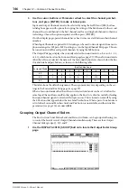
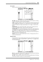
CURVE:
This displays the Compressor curve (i.e., input level vs. output level).
TYPE:
This is the comp type used by the currently selected channel’s Compressor.
Meters:
These meters indicate the levels of the currently selected Input Channel and its
horizontal or vertical partner. The GR meter indicates the amount of gain reduction being
applied by the currently selected channel’s Compressor.
ON/OFF:
This turns the currently selected channel’s Compressor on and off. It works in
unison with the SELECTED CHANNEL DYNAMICS [COMP ON] button.
PARAMETER:
These controls are used to set the Threshold, Ratio, Attack, Release, Out
Gain, and Knee (Width) parameters.
Grouping Output Channel Compressors
The Bus Out, Aux Send, Matrix Send, and Stereo Out Compressors can be grouped, allow-
ing you to control the compression of several Output Channels simultaneously. There are
four Output Channel Compressor groups: m, n, o, and p.
1
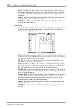
Use the DISPLAY ACCESS [GROUP] button to locate the Output Comp Link
page.
2
Press the LAYER [MASTER] button.
3
Use the Up/Down cursor buttons to select Comp groups m–p.
The selected group is highlighted by a flashing cursor box.
4
Use the [SEL] buttons to add and remove Output Channels to and from the
selected group.
The Compressor settings of the first Output Channel added to the group are applied to all
subsequently added Output Channels.
When an Output Channel is added to a group, its [SEL] button indicator lights up.

