background image

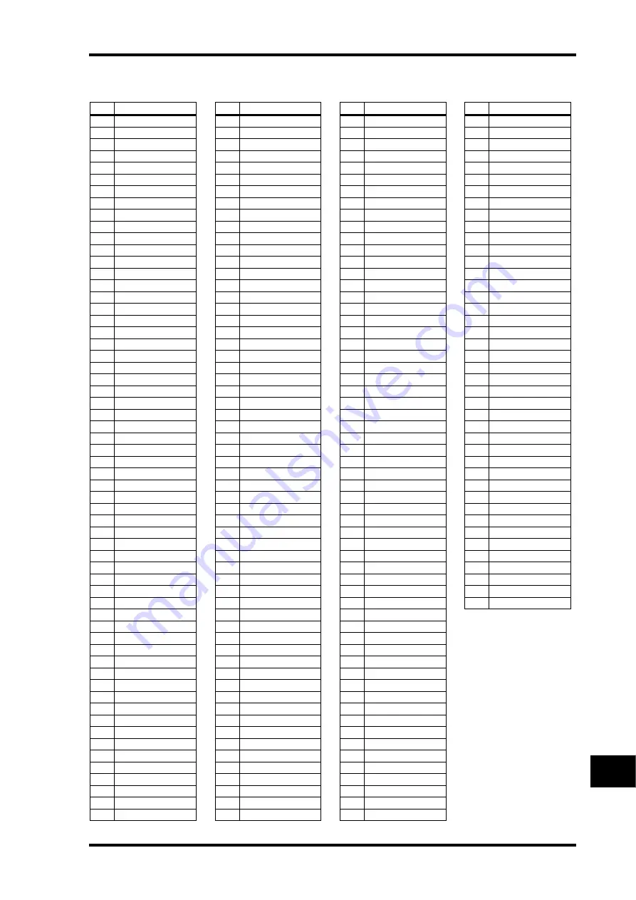
GPI Trigger Source & Target List

305

DM1000 Version 2—Owner’s Manual

Appendix

OUTPUT

#

Target

0

NO ASSIGN

1

CH1 FADER ON

2

CH2 FADER ON

3

CH3 FADER ON

4

CH4 FADER ON

5

CH5 FADER ON

6

CH6 FADER ON

7

CH7 FADER ON

8

CH8 FADER ON

9

CH9 FADER ON

10

CH10 FADER ON

11

CH11 FADER ON

12

CH12 FADER ON

13

CH13 FADER ON

14

CH14 FADER ON

15

CH15 FADER ON

16

CH16 FADER ON

17

CH17 FADER ON

18

CH18 FADER ON

19

CH19 FADER ON

20

CH20 FADER ON

21

CH21 FADER ON

22

CH22 FADER ON

23

CH23 FADER ON

24

CH24 FADER ON

25

CH25 FADER ON

26

CH26 FADER ON

27

CH27 FADER ON

28

CH28 FADER ON

29

CH29 FADER ON

30

CH30 FADER ON

31

CH31 FADER ON

32

CH32 FADER ON

33

CH33 FADER ON

34

CH34 FADER ON

35

CH35 FADER ON

36

CH36 FADER ON

37

CH37 FADER ON

38

CH38 FADER ON

39

CH39 FADER ON

40

CH40 FADER ON

41

CH41 FADER ON

42

CH42 FADER ON

43

CH43 FADER ON

44

CH44 FADER ON

45

CH45 FADER ON

46

CH46 FADER ON

47

CH47 FADER ON

48

CH48 FADER ON

49

BUS1 FADER ON

50

BUS2 FADER ON

51

BUS3 FADER ON

52

BUS4 FADER ON

53

BUS5 FADER ON

54

BUS6 FADER ON

55

BUS7 FADER ON

56

BUS8 FADER ON

57

AUX1 FADER ON

58

AUX2 FADER ON

59

AUX3 FADER ON

60

AUX4 FADER ON

61

AUX5 FADER ON

62

AUX6 FADER ON

63

AUX7 FADER ON

64

AUX8 FADER ON

65

STEREO FADER ON

66

CH1 FADER OFF

67

CH2 FADER OFF

68

CH3 FADER OFF

69

CH4 FADER OFF

70

CH5 FADER OFF

71

CH6 FADER OFF

72

CH7 FADER OFF

73

CH8 FADER OFF

74

CH9 FADER OFF

75

CH10 FADER OFF

76

CH11 FADER OFF

77

CH12 FADER OFF

78

CH13 FADER OFF

79

CH14 FADER OFF

80

CH15 FADER OFF

81

CH16 FADER OFF

82

CH17 FADER OFF

83

CH18 FADER OFF

84

CH19 FADER OFF

85

CH20 FADER OFF

86

CH21 FADER OFF

87

CH22 FADER OFF

88

CH23 FADER OFF

89

CH24 FADER OFF

90

CH25 FADER OFF

91

CH26 FADER OFF

92

CH27 FADER OFF

93

CH28 FADER OFF

94

CH29 FADER OFF

95

CH30 FADER OFF

96

CH31 FADER OFF

97

CH32 FADER OFF

98

CH33 FADER OFF

99

CH34 FADER OFF

100

CH35 FADER OFF

101

CH36 FADER OFF

102

CH37 FADER OFF

103

CH38 FADER OFF

104

CH39 FADER OFF

105

CH40 FADER OFF

106

CH41 FADER OFF

107

CH42 FADER OFF

108

CH43 FADER OFF

109

CH44 FADER OFF

110

CH45 FADER OFF

111

CH46 FADER OFF

112

CH47 FADER OFF

113

CH48 FADER OFF

114

BUS1 FADER OFF

115

BUS2 FADER OFF

116

BUS3 FADER OFF

117

BUS4 FADER OFF

118

BUS5 FADER OFF

119

BUS6 FADER OFF

#

Target

120

BUS7 FADER OFF

121

BUS8 FADER OFF

122

AUX1 FADER OFF

123

AUX2 FADER OFF

124

AUX3 FADER OFF

125

AUX4 FADER OFF

126

AUX5 FADER OFF

127

AUX6 FADER OFF

128

AUX7 FADER OFF

129

AUX8 FADER OFF

130

STEREO FADER OFF

131

CH1 FADER TALLY

132

CH2 FADER TALLY

133

CH3 FADER TALLY

134

CH4 FADER TALLY

135

CH5 FADER TALLY

136

CH6 FADER TALLY

137

CH7 FADER TALLY

138

CH8 FADER TALLY

139

CH9 FADER TALLY

140

CH10 FADER TALLY

141

CH11 FADER TALLY

142

CH12 FADER TALLY

143

CH13 FADER TALLY

144

CH14 FADER TALLY

145

CH15 FADER TALLY

146

CH16 FADER TALLY

147

CH17 FADER TALLY

148

CH18 FADER TALLY

149

CH19 FADER TALLY

150

CH20 FADER TALLY

151

CH21 FADER TALLY

152

CH22 FADER TALLY

153

CH23 FADER TALLY

154

CH24 FADER TALLY

155

CH25 FADER TALLY

156

CH26 FADER TALLY

157

CH27 FADER TALLY

158

CH28 FADER TALLY

159

CH29 FADER TALLY

160

CH30 FADER TALLY

161

CH31 FADER TALLY

162

CH32 FADER TALLY

163

CH33 FADER TALLY

164

CH34 FADER TALLY

165

CH35 FADER TALLY

166

CH36 FADER TALLY

167

CH37 FADER TALLY

168

CH38 FADER TALLY

169

CH39 FADER TALLY

170

CH40 FADER TALLY

171

CH41 FADER TALLY

172

CH42 FADER TALLY

173

CH43 FADER TALLY

174

CH44 FADER TALLY

175

CH45 FADER TALLY

176

CH46 FADER TALLY

177

CH47 FADER TALLY

178

CH48 FADER TALLY

179

BUS1 FADER TALLY

#

Target

180

BUS2 FADER TALLY

181

BUS3 FADER TALLY

182

BUS4 FADER TALLY

183

BUS5 FADER TALLY

184

BUS6 FADER TALLY

185

BUS7 FADER TALLY

186

BUS8 FADER TALLY

187

AUX1 FADER TALLY

188

AUX2 FADER TALLY

189

AUX3 FADER TALLY

190

AUX4 FADER TALLY

191

AUX5 FADER TALLY

192

AUX6 FADER TALLY

193

AUX7 FADER TALLY

194

AUX8 FADER TALLY

195

ST FADER TALLY

196

UDEF1 LATCH

197

UDEF2 LATCH

198

UDEF3 LATCH

199

UDEF4 LATCH

200

UDEF5 LATCH

201

UDEF6 LATCH

202

UDEF7 LATCH

203

UDEF8 LATCH

204

UDEF9 LATCH

205

UDEF10 LATCH

206

UDEF11 LATCH

207

UDEF12 LATCH

208

UDEF1 UNLATCH

209

UDEF2 UNLATCH

210

UDEF3 UNLATCH

211

UDEF4 UNLATCH

212

UDEF5 UNLATCH

213

UDEF6 UNLATCH

214

UDEF7 UNLATCH

215

UDEF8 UNLATCH

216

UDEF9 UNLATCH

217

UDEF10 UNLATCH

218

UDEF11 UNLATCH

219

UDEF12 UNLATCH

220

REC LAMP

221

POWER ON

#

Target

Содержание DM 1000

Страница 1: ...Owner s Manual Owner s Manual Keep This Manual For Future Reference Keep This Manual For Future Reference E ...

Страница 2: ...d to the terminal in the plug which is marked by the letter E or by the safety earth symbol or colored GREEN or GREEN and YELLOW The wire which is coloured BLUE must be connected to the terminal which is marked with the letter N or coloured BLACK The wire which is coloured BROWN must be connected to the termi nal which is marked with the letter L or coloured RED This applies only to products distr...

Страница 3: ...es and a third grounding prong The wide blade or the third prong are provided for your safety If the pro vided plug does not fit into your outlet consult an electrician for replacement of the obsolete outlet 10 Protect the power cord from being walked on or pinched particularly at plugs convenience receptacles and the point where they exit from the apparatus 11 Only use attachments accessories spe...

Страница 4: ...ical storms When removing the electric plug from the device or an outlet always hold the plug itself and not the cord Pulling by the cord can damage it When transporting or moving the device always use two or more people Before moving the device remove all connected cables When you move the device with the MB1000 attached do not permit impact or stress on the cable connector that connects the MB10...

Страница 5: ...y save the data to an external media using MIDI Bulk Dump then have qualified Yamaha service personnel replace the backup battery Using a mobile telephone near this unit may induce noise If noise occurs use the telephone away from the unit The digital circuits of this unit may induce a slight noise into nearby radios and TVs If noise occurs relocate the affected equipment When connecting D sub cab...

Страница 6: ...iscusses a specific section or function of the DM1000 The Input and Output Channels are explained in the following chapters Input Channels Bus Outs and Aux Sends Where possible these chapters have been organized in order of sig nal flow from input to output Conventions Used in this Manual The DM1000 features two types of buttons physical buttons that you can press e g ENTER and DISPLAY and buttons...

Страница 7: ...page 120 Raising the channel faders for soloed Channels from can unsolo the Channels page 121 You can simultaneously select 2TR D1 or 2TR D2 and STEREO as control room monitor sources page 123 Surround Function The on off status of the Follow Pan button is reflected in the pan and Surround Pan settings page 125 The Surround Monitor function now supports THX Surround page 138 You can simultaneously...

Страница 8: ...Cubase SX and General DAW This enables you to control these devices using the DM1000 s SELECTED CHANNEL section Controllable functions vary depending on the DAW software and ver sion you are using Other Functions You can control the DM1000 from a connected Video Editor via the ESAM protocol page 259 You can set the Routing ST Pair Link so that the routing from paired channels to the Stereo Bus is ...

Страница 9: ...3 Analog Inputs Outputs 53 Digital Inputs Outputs 54 Converting Sampling Rates of Signals Received at 2TR Digital Inputs 55 Monitoring Digital Input Channel Status 57 Dithering Digital Outputs 58 Setting the Transfer Format for Higher Sampling Rates 59 6 Input Channels 61 About Input Channels 61 Setting the Input Channels from the Display 63 Setting the Input Channels from the Control Surface 75 P...

Страница 10: ...olo Function 121 Using the Control Room Monitor 122 Using the Talkback Function 123 11 Surround Functions 125 Using Surround Pan 125 Surround Monitoring 136 12 Grouping Channels Linking Parameters 147 Grouping Linking 147 Using Fader Groups and Mute Groups 148 Using Fader Group Master 150 Using Mute Group Master 152 Linking EQ and Compressor Parameters 152 13 Internal Effects 155 About the Interna...

Страница 11: ...tup 246 Assigning Scenes to Program Changes for Remote Recall 249 Assigning Parameters to Control Changes for Real time Control 250 Controlling Parameters by Using Parameter Changes 256 Transmitting Parameter Settings via MIDI Bulk Dump 256 19 Controlling the DM1000 from a Video Editor 259 About ESAM 259 Connection Example 259 Crossfade via ESAM Commands 260 Video Editors with confirmed compatibil...

Страница 12: ...ters fs 44 1 kHz 325 Dynamics Parameters 327 Appendix B Specifications 332 General Spec 332 Libraries 337 Analog Input Spec 337 Analog Output Spec 337 Digital Input Spec 338 Digital Output Spec 338 I O Slot Spec 1 2 339 Control I O Spec 339 REMOTE Port 340 CONTROL Port 340 Dimensions 341 Appendix C MIDI 343 Scene Memory to Program Change Table 343 Initial Parameter to Control Change Table 344 MIDI...

Страница 13: ...isplay with fluorescent backlighting Buttons and controls in the SELECTED CHANNEL section enable direct editing of channel mix parameters 12 USER DEFINED KEYS enable you to assign functions to control DM1000 internal parameters Two expansion slots for optional digital I O AD and DA cards Sonic Specifications Linear 24 bit 128 times oversampling A D converters Linear 24 bit 128 times oversampling D...

Страница 14: ... Scene Memory Scene memories for storing and recalling the mix settings as Scenes Snapshot style automation with Scene memories recallable via Automix Surround Sound Supports 3 1 5 1 and 6 1 channel surround sound production Joystick for adjusting each channel s surround pan Automix Automated controls of channel faders and parameters via Automix Even more power ful when combined with an MTR DAW an...

Страница 15: ...60 70 50 40 30 20 15 10 10 5 0 5 ON SOLO SEL AUX 6 6 6 22 38 0 5 10 15 20 30 40 50 60 70 50 40 30 20 15 10 10 5 0 5 ON SOLO SEL AUX 7 7 7 23 39 0 5 10 15 20 30 40 50 60 70 50 40 30 20 15 10 10 5 0 5 ON SOLO SEL AUX 8 8 8 24 40 0 5 10 15 20 30 40 50 60 70 50 40 30 20 15 10 10 5 0 5 ON SOLO SEL BUS 1 9 9 25 41 0 5 10 15 20 30 40 50 60 70 50 40 30 20 15 10 10 5 0 5 ON SOLO SEL 0 5 10 15 20 30 40 50 6...

Страница 16: ...bricate your own cover and attach it to the front panel to prevent the controls from being operated inadvertently Yamaha does not sell such a cover If you fabricate and attach your own cover make sure that the mounting screws do not extend more than 10 mm into the front panel You will need to allow approximately 15 20 mm between the top panel and the cover in order to clear the control knobs and b...

Страница 17: ...ou to select channels for Automix recording and playback create or cancel channel pairs and add channels to or remove them from Fader Mute EQ and Compressor groups C SOLO buttons 1 16 These buttons solo the selected channels The SOLO button indicator of the cur rently soloed channel lights up D ON buttons 1 16 These buttons turn the selected channels on or off The ON button indicators for On chann...

Страница 18: ... button the button indicator turns on and Encoders 1 16 function as chan nel Aux Send The Send destination is selected in the AUX SELECT Section D ASSIGN button If you press this button the button indicator turns on and Encoders 1 16 function as assignable controls for the parameters assigned on the Encoder pages By default Input Patches of the corresponding Input Channels are assigned FADER MODE ...

Страница 19: ...ut levels see page 39 H VIEW button This button displays aView page enabling you to view and set mix parameters for a specific channel see page 72 I PAIR GROUP button This button displays a Pair Group page enabling you to pair channels group multiple fad ers or mute channels see page 78 and 147 J INSERT DELAY button This button displays a INS DLY page enabling you to switch the signal phase set th...

Страница 20: ... segment level meters display the final output level of the Stereo Bus C Contrast control This control adjusts the display contrast D F1 F4 buttons These buttons select a page from a multi page screen Selecting a tab at the bottom of the screen using one of these buttons displays the corresponding page See page 30 for more information on displaying a page E Left Tab Scroll button F Right Tab Scrol...

Страница 21: ...H button G EQUALIZER HIGH MID button H EQUALIZER LOW MID button I EQUALIZER LOW button These buttons select the EQ band HIGH HIGH MID LOW MID LOW The corre sponding button indicator of the currently selected band lights up J EQUALIZER Q control This control adjusts the currently selected band Q K EQUALIZER FREQUENCY control This control adjusts the currently selected band frequency L EQUALIZER GAI...

Страница 22: ...e 33 for more information on the Master Layer SCENE MEMORY Section A Scene memory display The number of the currently selected Scene memory is displayed here B Edit indicator If you adjust a mix parameter after a Scene has been recalled or stored a dot flashes here C STORE button This button enables you to store the current mix settings See page 163 for more informa tion on Scene Memories D Scene ...

Страница 23: ...crementaparametervaluebyone Pressingthe INC button increments the value pressing the DEC button decrements the value Holding down either key increments or decrements the value con tinuously D Left Right Up Down cursor buttons These buttons move the cursor around the display pages or select parameters and options Holding down a cursor button moves the cursor continuously in the respective direction...

Страница 24: ...nalsource Whenthe BUS buttonindicator is lit the Bus 1 8 signals are selected When the SLOT button indicator is lit the signals from Slots 1 2 are selected See page 136 for more information on the Surround Monitor I DIMMER button This button activates the Dimmer function which lowers the Monitor and Surround Mon itor signals This function is convenient when you wish to talk in the control room dur...

Страница 25: ...anced XLR 3 32 type con nectors output any Bus signals and channel Direct Out signals The nomi nal signal level is 4 dB WORD CLOCK IN OUT CONTROL IN OUT TO HOST USB REMOTE MIDI SMPTE IN COAXIAL AES EBU COAXIAL AES EBU 2 2 1 2TR IN DIGITAL METER 1 SLOT SLOT INPUT OMNI IN 2 3 4 5 6 7 8 1 10 11 12 13 14 15 9 2 3 4 5 6 7 8 1 10 11 12 9 2 1 3 16 4 AC IN POWER ON OFF AD Input and Output Section p 25 Pow...

Страница 26: ...otely control external equipment that supports the Yamaha AD8HR AD824 and Sony P2 Protocol remote control commands that are used on TASCAM DA 98HR and other professional video recorders Use a reverse cable to connect an AD8HR AD824 and use a straight cable to connect a P2 Protocol device Use a reverse cable to connect two DM1000s to each other Connecting two DM1000s to each other enables communica...

Страница 27: ... recorder or CD recorder L 2TR IN DIGITAL COAXIAL 2 This phono connector accepts consumer format IEC 60958 digital audio The connector is typically used to connect the digital stereo output consumer format of a DAT recorder MD recorder or CD recorder Power Section A Grounding screw Be sure to use this screw to ground the DM1000 to protect yourself against electrical shock The supplied power cord f...

Страница 28: ...ails and slide it all the way into the slot as shown below You may have to push firmly to fully insert the card into the internal connector 4 Secure the card using the attached thumbscrews Tighten the screws firmly or else the card may not be grounded correctly which may cause the DM1000 to malfunction WORD CLOCK IN OUT CONTROL IN OUT TO HOST USB REMOTE MIDI SMPTEIN COAXIAL AES EBU COAXIAL AES EBU...

Страница 29: ...T L ST R The second four characters are the channel s Short name You can edit the channel s Short name if you desire see page 79 and 91 C Current Scene This section indicates the number and title of the currently selected Scene memory see page 164 If the selected Scene is write protected a padlock icon appears D EDIT indicator Thisindicatorappearswhenthecurrentmixsettingsnolongermatchthoseof theSc...

Страница 30: ...ing SEL button or the cursor buttons L Page area This page area displays various page contents M Page tabs These tabs enable you to select a display page N Tab Scroll arrows These arrows indicate that more pages are available Selecting Display Pages To select a display page 1 Press the corresponding button on the top panel to select the desired page group Display pages are grouped by function To s...

Страница 31: ...ou want to adjust then rotate the Parameter wheel or press the INC DEC buttons to modify the value Buttons The buttons enable you to turn certain functions on enabled or off disabled Move the cursor to the appropriate button then press the ENTER button to turn the function on high lighted or off The buttons also enable you to select one of two options or to execute certain functions Parameter Boxe...

Страница 32: ...the right shows lowercase characters and numbers Use the cursor buttons to select characters and press the ENTER button to enter them into the title The cursor moves to the right automatically as each character is entered To move the cursor accross the title use the Parameter wheel or the left and right arrows in the display page Use the SHIFT LOCK button to select uppercase or lowercase character...

Страница 33: ...50 60 70 50 40 30 20 15 10 10 5 0 5 AUX 7 7 23 39 0 5 10 15 20 30 40 50 60 70 50 40 30 20 15 10 10 5 0 5 AUX 8 8 24 40 0 5 10 15 20 30 40 50 60 70 50 40 30 20 15 10 10 5 0 5 BUS 1 9 25 41 0 5 10 15 20 30 40 50 60 70 50 40 30 20 15 10 10 5 0 5 0 5 10 15 20 30 40 50 60 70 50 40 30 20 15 10 10 5 0 5 0 5 10 15 20 30 40 50 60 70 50 40 30 20 15 10 10 5 0 5 0 5 10 15 20 30 40 50 60 70 50 40 30 20 15 10 1...

Страница 34: ...rsor moves to that parameterautomatically If thecurrently displayedpagecontainsnosuchparameter apage that does contain such a parameter is selected automatically 3 To select the Stereo Out press the STEREO SEL button or touch the STE REO fader Repeatedly pressing the STEREO SEL button toggles between the Stereo Out left and Ste reo Out right channels If the currently displayed page contains a rele...

Страница 35: ...uttons Fader Mode Channel Strip Fader 1 8 9 16 1 16 button Fader Input Channels 1 16 level Aux Input Channels 1 16 Aux Send level 17 32 button Fader Input Channels 17 32 level Aux Input Channels 17 32 Aux Send level 33 48 button Fader Input Channels 33 48 level Aux Input Channels 33 48 Aux Send level REMOTE 1 button Fader Operation depends on the selected target see page 215 Aux No operation No op...

Страница 36: ... for each Layer and Encoder mode LAYER buttons Encoder Mode Channel Strip Encoder 1 8 9 16 1 16 button Pan Input Channels 1 16 pan Aux Input Channels 1 16 Aux Send level Assign Assigned parameter1 1 If ALT LAYER is assigned the Encoder controls the parameters assigned to the faders of the layer that is currently not selected if Layer 1 16 is currently selected the Encoder controls the parameters a...

Страница 37: ...ight handbox Theparametercurrently assignedtothebuttonishighlightedinthe right hand box 2 Use the Parameter wheel or press the INC DEC buttons to select a param eter in the right hand box A parameter is selected when it appears inside the dotted box Refer to the next page for a complete list of assignable parameters 3 Press ENTER to confirm the assignment Once assigned press the ENCODER MODE ASSIG...

Страница 38: ... Mid Q 20 EQ Low Mid F EQ Low Mid Frequency 21 EQ Low Mid G EQ Low Mid Gain 22 EQ High Mid Q EQ High Mid Q 23 EQ High Mid F EQ High Mid Frequency 24 EQ High Mid G EQ High Mid Gain 25 EQ High Q EQ High Q 26 EQ High F EQ High Frequency 27 EQ High G EQ High Gain 28 Gate On Gate on off 29 Gate Threshold Gate Threshold 30 Gate Range Gate Range 31 Gate Attack Gate Attack 32 Gate Decay Gate Decay 33 Gate...

Страница 39: ...ion then press ENTER You can select one of the following three positions in each section PRE EQ Immediately before EQ PRE FADER Immediately before the fader POST FADER Immediately after the fader 3 Press the DISPLAY ACCESS METER button repeatedly until the page listed below that contains the desired channels appears CH1 32 page CH33 48 page These pages display the Input Channel 1 32 levels and Inp...

Страница 40: ...e COMP GR The amount of gain reduction for the compressor LEVEL Input Channel input level or Output Channel output level Tip You can also select the CH1 32 page the CH33 48 page or the Master page using the LAYER buttons In this case if an optional MB1000 Peak Meter Bridge is installed the Peak Meter Bridge displays the same signal meters in unison with the DM1000 meters Tip Thesepagesalsoallowyou...

Страница 41: ...he Meter Master page the ST meter on the Stereo page and the stereo meter on the right side of the display 6 To activate the Peak Hold function move the cursor to the PEAK HOLD but ton then press ENTER The PEAK HOLD button turns on and the peak level is held on the meters on the page and on the Peak Meter Bridge To cancel the Peak Hold function turn the PEAK HOLD button off If an optional MB1000 P...

Страница 42: ...42 Chapter 3 Operating Basics DM1000 Version 2 Owner s Manual ...

Страница 43: ...SEL AUX 3 3 3 19 35 0 5 10 15 20 30 40 50 60 70 50 40 30 20 15 10 10 5 0 5 ON SOLO SEL AUX 4 4 4 20 36 0 5 10 15 20 30 40 50 60 70 50 40 30 20 15 10 10 5 0 5 ON SOLO SEL AUX 5 5 5 21 37 0 5 10 15 20 30 40 50 60 70 50 40 30 20 15 10 10 5 0 5 ON SOLO SEL AUX 6 6 6 22 38 0 5 10 15 20 30 40 50 60 70 50 40 30 20 15 10 10 5 0 5 ON SOLO SEL AUX 7 7 7 23 39 0 5 10 15 20 30 40 50 60 70 50 40 30 20 15 10 10...

Страница 44: ... 20 30 40 50 60 70 50 40 30 20 15 10 10 5 0 5 ON SOLO SEL AUX 5 5 5 21 37 0 5 10 15 20 30 40 50 60 70 50 40 30 20 15 10 10 5 0 5 ON SOLO SEL AUX 6 6 6 22 38 0 5 10 15 20 30 40 50 60 70 50 40 30 20 15 10 10 5 0 5 ON SOLO SEL AUX 7 7 7 23 39 0 5 10 15 20 30 40 50 60 70 50 40 30 20 15 10 10 5 0 5 ON SOLO SEL AUX 8 8 8 24 40 0 5 10 15 20 30 40 50 60 70 50 40 30 20 15 10 10 5 0 5 ON SOLO SEL BUS 1 9 9 ...

Страница 45: ...0 50 40 30 20 15 10 10 5 0 5 ON SOLO SEL AUX 3 3 3 19 35 0 5 10 15 20 30 40 50 60 70 50 40 30 20 15 10 10 5 0 5 ON SOLO SEL AUX 4 4 4 20 36 0 5 10 15 20 30 40 50 60 70 50 40 30 20 15 10 10 5 0 5 ON SOLO SEL AUX 5 5 5 21 37 0 5 10 15 20 30 40 50 60 70 50 40 30 20 15 10 10 5 0 5 ON SOLO SEL AUX 6 6 6 22 38 0 5 10 15 20 30 40 50 60 70 50 40 30 20 15 10 10 5 0 5 ON SOLO SEL AUX 7 7 7 23 39 0 5 10 15 2...

Страница 46: ...Wordclock connections To establish wordclock synchronization between the DM1000 and external devices you can distribute wordclock signals independently via dedicated cables or you can use clock infor mation derived from digital audio connections The WORD CLOCK IN and OUT connectors transmit and receive wordclock signals inde pendently on the DM1000 The following examples show two ways in which wor...

Страница 47: ...48V ON OFF 48V ON OFF 48V ON OFF 48V ON OFF 48V ON OFF 48V ON OFF 48V ON OFF 48V ON OFF 48V ON OFF 48V ON OFF 48V ON OFF 48V ON OFF 48V ON OFF 48V 0 5 10 15 20 30 40 50 60 70 50 40 30 20 15 10 10 5 0 5 ON SOLO SEL AUX 1 1 1 17 33 0 5 10 15 20 30 40 50 60 70 50 40 30 20 15 10 10 5 0 5 ON SOLO SEL AUX 2 2 2 18 34 0 5 10 15 20 30 40 50 60 70 50 40 30 20 15 10 10 5 0 5 ON SOLO SEL AUX 3 3 3 19 35 0 5 ...

Страница 48: ...E column displays the names of any installed I O cards The number of pairs depends on the type of I O card installed WC IN This button selects the wordclock signal input at the WORD CLOCK IN connector on the rear panel 2TRD1 This button selects the 2TR IN DIGITAL 1 input as the word clock source 2TRD2 This button selects the 2TR IN DIGITAL 2 input as the word clock source INT 44 1k INT 48k INT 88 ...

Страница 49: ...Follow the steps below to view or change the patching 1 Press the DISPLAY ACCESS INPUT PATCH button repeatedly until the fol lowing page appears Inputs and Slot channels that are currently assigned to Input Channels are shown in the parameter boxes 1 beneath the channel numbers The parameter indicators are explained below No assignment AD1 AD16 INPUT connectors 1 16 OMN1 OMN4 OMNI IN connectors 1 ...

Страница 50: ...the patching 1 Press the DISPLAY ACCESS OUTPUT PATCH button repeatedly until the fol lowing page appears Signals that are currently assigned to the OMNI OUT connectors are shown in the param eter boxes 1 underneath the connector numbers The parameter indicators are explained below No assignment BUS1 BUS8 Bus 1 8 signals AUX1 AUX8 Aux Send 1 8 Signals ST L R Stereo Bus signals INS CH1 INS CH48 Inpu...

Страница 51: ... Outs CAS ST L ST R Stereo Bus Cascade Outs CASSOLOL CASSOLOR Solo Bus Cascade Outs SOLO L SOLO R Solo signals M MX XXX XXX is a channel name Surround Monitor Outs 2 Use the cursor buttons to move the cursor to a patch parameter 1 you wish to change and rotate the Parameter wheel or press the INC DEC buttons to modify the patching 3 Press ENTER to confirm the change Tip To restore the default patc...

Страница 52: ...52 Chapter 4 Connections and Setup DM1000 Version 2 Owner s Manual ...

Страница 53: ...nal input range is 60 dB through 4 dB OMNI IN connectors 1 4 These balanced XLR 3 31 type connectors accept line level signals The nominal signal level is 4 dB Phantom Power Inputs 1 through 16 feature switchable 48V phantom powering for use with condenser type microphones and direct boxes Individual 48V ON OFF switches on each input turn phantom power on and off PAD switches Inputs 1 through 16 f...

Страница 54: ... 2TR IN DIGITAL 2 is an RCA phono connector and accepts con sumer format IEC 60958 digital audio You can patch signals input at these connectors to any Input Chan nels see page 114 You can monitor these inputs via the Control Room monitors by using the MONITOR 2TR D1 and 2TR D2 buttons 2TR OUT DIGITAL connectors These connectors output signals to a DAT or other 2 track digital recorder or consumer...

Страница 55: ... 48 kHz Phone jack balanced x8 MY8 AD241 1 This card is a substitution for a 20 bit MY8 AD card 24 bit 44 1 48 kHz MY4 AD 4 XLR 3 31 type balanced x4 MY8 AD96 8 24 bit 44 1 48 88 2 96 kHz D sub 25 pin MY4 DA Analog out 4 20 bit 44 1 48 kHz XLR 3 32 type balanced x4 MY8 DA96 8 24 bit 44 1 48 88 2 96 kHz D sub 25 pin MY8 ADDA96 Analog in out 8 8 Euroblock x4 MY8 AE2 2 These cards support 24 bit 96 k...

Страница 56: ...convert the sampling rate of the signals input at the installed I O card inputs press the DISPLAY ACCESS DIO button then press the F2 button The DIO Format page appears Use the buttons in the SRC sections 1 to turn the sampling rate converters on and off You can turn the sampling rate converters of the digital I O cards on or off in pairs odd even channels in this order Tip The FS box displays the...

Страница 57: ...e use the following buttons to select a slot or connector for which you want to view the channel status A SLOT1 SLOT2 These buttons enable you to view the Channel Status of each two adjacent odd and even in this order channel signals connected to the digital I O cards installed in Slots 1 and 2 B 2TR IN This button enables you to view the Channel Status of input signals connected to the 2TR Digita...

Страница 58: ...ght corner of the screen to select a channel group you wish to display Parameter values Description General Temporarily used Laser Optical Laser optical device D D Conv Digital Digital converter and signal processing device Magnetic Magnetic tape device and magnetic disk device D Broadcast Digital broadcast reception Instruments Musical instrument microphone and sources that generate string signal...

Страница 59: ...h ering and rotate the Parameter wheel or press the INC DEC buttons to select the value that matches the resolution of the receiving device Setting the Transfer Format for Higher Sampling Rates To operate the DM1000 at higher sampling frequencies 88 2 kHz or 96 kHz and transfer digital audio signals to and from connected external devices you must set the data transfer format in accordance with the...

Страница 60: ...gital audio data is received and transmitted at the current higher sampling rate i e 88 2 kHz or 96 kHz Select this mode if the devices that support the higher sampling rates transmit or receive data SINGLE In Single mode digital audio data is received and transmitted at a sampling rate that is half 44 1 48 kHz the current higher sampling rate of the DM1000 For example this is useful when you wish...

Страница 61: ...s compressor expander or limiter The compressor can be pre EQ pre fader or post fader ATT Attenuator This section enables you to attenuate or amplify the level of signals that will be input to the EQ The attenuator enables you to prevent post EQ signals from clipping and to correct sig nal levels that are too low 4 BAND EQ 4 band equalizer This parametric EQ features four bands high high mid low m...

Страница 62: ...Aux Out 1 8 The signals can be routed to Aux Sends from either the pre fader or post fader position INSERT This section enables you to patch input signals to external devices via the on board I O con nectors or I O cards or insert the internal effect processors METER This section enables you to switch the metering position of the signal levels that are dis played in the Meter page or on the option...

Страница 63: ...ER or INC DEC buttons to change the setting A NOR REV These buttons switch the corresponding Input Channel phase NOR buttons indicate normal phase and REV buttons indicate reversed phase B GLOBAL The GLOBAL NOR REV buttons allow you to set the phase for all Input Channels simultaneously Delaying Input Channels To set the delay for each channel press the INSERT DELAY button repeatedly until the pag...

Страница 64: ...ple beat frame The delay time can be set using units of meters feet samples beats or frames which you select by using the DELAY SCALE buttons MIX This parameter sets the mix balance of dry Input Channel and wet delayed signals FB GAIN This parameter sets the amount of delay feedback Tip The delay time range depends on the sampling rate at which the DM1000 is operating For example at 44 1 kHz the r...

Страница 65: ... bus in the parameter box below the AUX button B STEREO LINK This parameter s ON OFF button enables you to pair gates for stereo operation even when the Input Channels are not paired C CURVE This area displays the current gate curve D TYPE This area displays the current gate type GATE or DUCKING E Meters These meters indicate the levels of the post gate signals and the amount of gain reduc tion F ...

Страница 66: ... paired C CURVE This area displays the current compressor curve D TYPE This field indicates the compressor type used by the currently selected channel s com pressor COMP EXPAND COMP H COMP S E Meters These meters indicate the levels of the post compressor signals and the amount of gain reduction F ON OFF The ON OFF button turns the currently selected Input Channel s compressor on or off G PARAMETE...

Страница 67: ... setting to all Input Channels including those not currently displayed on the screen To do this move the cur sor to the source knob that you wish to copy then double click the ENTER button The confirmation window appears Select YES to execute the copy operation You can also set the amount of attenuation in bits To set the amount in bits in the range of 2 bits to 24 bits move the cursor to the desi...

Страница 68: ... described below A EQ ON The ON OFF button turns the currently selected Input Channel s EQ on or off You can press the ENTER button to turn the EQ on or off as long as the cursor is located on any parameter other than TYPE B TYPE Selects the type of EQ TYPE I is the EQ type used on legacy Yamaha 02R series digital mixing consoles TYPE II is a newly developed algorithm C ATT Determines the amount o...

Страница 69: ...1 dB steps 1 1 The LOW and HIGH GAIN controls function as filter on off controls when Q is set to HPF or LPF respectively Tip TheLOW bandEQfunctionsasahigh passfilterwhentheQparameterintheLOWsection is set to HPF It functions as a shelving type EQ when the Q parameter is set to L SHELF The HIGH band EQ functions as a low pass filter when the Q parameter in the HIGH sec tionissettoLPF Itfunctionsas...

Страница 70: ...eset the currently selected Pan control to center B MODE The MODE parameter determines how paired Input Channels are panned There are three Pan modes as follows INDIVIDUAL In Individual mode paired Input Channel pan controls operate independently GANG In Gang mode paired Input Channel pan controls operate in unison maintaining the current pan range INV GANG In Inverse Gang mode paired Input Channe...

Страница 71: ...ns determine whether the Input Channel s Pan setting is applied to the Bus Outs In surround mode they also determine whether the Surround Pan setting is applied to the Bus Outs B Bus buttons 1 8 These buttons route the currently selected Input Channel to the Bus Outs If the DM1000 is in Surround mode the button indicators change as follows depending on the selected Surround mode L Left R Right C C...

Страница 72: ...EQ Settings To display the View Parameter page for a specific Input Channel use the corresponding SEL button or fader to select the desired channel then press the DISPLAY ACCESS VIEW button then the F1 button Move the cursor to a parameter you wish to change and rotate the Parameter wheel or press the INC DEC buttons or ENTER button to modify the setting A GATE section This section enables you to ...

Страница 73: ...age of a certain Input Channel use the corresponding SEL button or fader to select the desired channel then press the DISPLAYACCESS VIEW but ton then the F2 button Move the cursor to a parameter you wish to change then rotate the Parameter wheel or press the INC DEC buttons to modify the setting A PAN ON Fader section PAN control This control adjusts the currently selected Input Channel s Pan para...

Страница 74: ...identical signal is sent to the paired Bus Outs In surround mode it also determines whether the Surround Pan setting is applied to the Bus Outs D AUX section AUX These controls set the currently selected Input Channel s Aux Send 1 8 levels and positions See page 93 for more informa tion on Aux Sends E Meter section Meters These meters indicate the levels of the currently selected Input Channel PRE...

Страница 75: ...ay pops up Routing and EQ ing Input Channels 1 Press the SEL button or move the fader for the channel you wish to control 2 To route each Input Channel use the following buttons in the SELECTED CHANNEL section ROUTING 1 8 buttons These buttons route the currently selected Input Channel to a Bus ROUTING STEREO button When this button is turned on Input Channel signals are routed to the Stereo Bus R...

Страница 76: ...ou can set this parameter for each channel independent ly on the EQ ATT page but the paired channel settings are linked on the EQ Edit and View pages To pair channels or to cancel channel pairs you can use the SEL buttons on the top panel or access the Pair Group pages Tip Pressing and holding down the button selected in Step 3 resets the corresponding band gain PressingtheSELECTEDCHANNEL HIGH and...

Страница 77: ...l parameter values to the odd channel RESET BOTH Resets both channel parameters to the default settings same as when Channel memory 01 is recalled Move the cursor to the desired button then press ENTER to confirm the pair Note The settings of the first channel are copied to the second channel and the channels are paired if the Pair Confirmation check box on the Preference1 page is not checked defa...

Страница 78: ...L This button pairs counterpart channels on Layer 1 and Layer 2 that share the same physical fader e g CH1 CH17 CH16 CH32 etc This mode is useful when you wish to use one fader to control both stereo channels When you switch the Pair Mode the combinations of channel numbers displayed on the page also change 3 Move the cursor to the desired channel s MONOx2 button then press ENTER The channels are ...

Страница 79: ...and Long full names in the right column 2 When the Name Input Auto Copy check box 3 is on the first four characters of a newly entered Long name are automatically copied to the Short name On the other hand a newly entered Short name is automatically added to the beginning of the Long name You can reset all channel names to their default names by moving the cursor to the INI TIALIZE button then pre...

Страница 80: ...the L connector to the input jack of an odd Input Chan nel and connect the R connector to the input jack of the partner channel 2 Press the PAIR GROUP button repeatedly until the Pair Group Input page appears 3 Turn on the MS button for the channels to which the MS microphone is con nected The two channels are automatically paired and MS Decoding is turned on With MS Decod ing turned on the faders...

Страница 81: ... dynamics processor can be used as compressor expander or limiter The processor can be located pre EQ pre STEREO fader or post STEREO fader ON On Off This button turns the Stereo Out on or off LEVEL The STEREO fader adjusts the Stereo Out output levels Balance This section enables you to adjust the level balance between the L and R channels of the Ste reo Out OUTPUT DELAY Output delay This section...

Страница 82: ...information refer to the explanation the Stereo Out see page 81 Bus to Stereo Bus Out 1 8 signals are also routed to the Stereo Bus In addition to the ON LEVEL and other parameters you can also set the Send Level On Off Pan and other parameters Tip You can also pair adjacent odd even buses in this order for stereo operation see page 89 Note By default channels 1 8 and 9 16 of Slots 1 and 2 are pat...

Страница 83: ...enuate the Bus Out 1 8 Aux Out 1 8 and Stereo Out signals The parameters on this page and the procedure for setting them are the same as for Input Channels except that this page does not include the bit shift parameters see page 67 Delaying the Stereo Out and Bus Outs To delay the Stereo Out and Bus Out 1 8 signals press the INSERT DELAY button repeatedly until the INS DLY Out Dly page appears The...

Страница 84: ...reo Out or Bus Out 1 8 The parameters on this page and the procedure for setting them are the same as for Input Channels see page 66 EQ ing the Stereo Out and Bus Outs To set the EQ for the Stereo Out and Bus Out 1 8 EQ press the EQUALIZER DISPLAY button repeatedly to display the EQ EQ Edit page and use the SEL buttons or faders to select the Stereo Out or Bus Out 1 8 The parameters on this page a...

Страница 85: ...Outs 1 8 as a Group Bus To patch the Bus Out 1 8 signals to the Stereo Bus press the SELECTED CHANNEL ROUTING DISPLAY button repeatedly to display the Routing Bus To St page Move the cursor to the desired parameter you wish to change then rotate the Parameter wheel or press the INC DEC buttons to modify the setting A TO ST PAN These controls pan the Bus Out 1 8 signals between the left and right S...

Страница 86: ... as for Input Channels except for the following items The Stereo Out and Bus Out 1 8 Parameter pages do not contain the Gate and Phase parameters The Stereo Out Parameter page does not contain the Pair parameter Viewing Faders and Other Parameters To display the View Fader page use the corresponding SEL button or fader to select the desired bus then press the DISPLAY ACCESS VIEW button then the F2...

Страница 87: ...r layer B Fader Thisfadersetsthecurrently selectedBusOut 1 8 level andlinkswiththefader 9 16 in the Master layer The fader knob is highlighted when the fader is set to 0 0 dB C TO ST PAN This control sets the Bus Out to Stereo Out Pan position for the currently selected Bus Out 1 8 D TO ST ON OFF This button turns on or off the Bus Out to Stereo Out signal for the currently selected Bus Out 1 8 E ...

Страница 88: ...ess the MASTER button in the LAYER section to select the Master layer then move faders 9 16 At this time you can turn Bus Out 1 8 on or off using the ON 9 16 buttons EQ ing the Stereo Out and Bus Outs 1 Press the SEL button or move the fader of the bus to which you want to apply EQ 2 To control the EQ of the currently selected bus select the desired band to adjust by pressing one of the following ...

Страница 89: ...he parameters on this page are described below A STEREO MONOx2 These buttons turn Bus or Aux Send pairs on or off B F S This button determines whether Aux Sends follow the Input Channel Surround Pan when the DM1000 is in a Surround mode When this button is turned on Aux Sends follow the Input Channel Surround Pan This is useful for feeding Surround signals to external Surround effects processors 2...

Страница 90: ...ge appears 2 Move the cursor in the left column 1 then scroll the list up or down using the Parameter wheel to select the desired output or slot channel for which you want to adjust attenuation The following outputs and slot channels can be selected OMNI OUT 1 12 OMNI OUT connectors 1 12 SLOT 1 1 through 1 16 Channels 1 16 of Slot 1 SLOT 2 1 through 2 16 Channels 1 16 of Slot 2 3 Move the cursor t...

Страница 91: ... names in the center column 1 and Long full names in the right column 2 When the Name Input Auto Copy check box 3 is on the first four characters of a newly entered Long name are automatically copied to the Short name You can reset all bus names to their default names by moving the cursor to the INITIALIZE button then pressing ENTER 2 Move the cursor to a name you wish to change then press ENTER T...

Страница 92: ...92 Chapter 7 Bus Outs DM1000 Version 2 Owner s Manual ...

Страница 93: ...rs The following diagram illustrates the Aux Out 1 8 signal flow INSERT ATT Attenuator 4 BAND EQ 4 band equalizer COMP Compressor ON On Off LEVEL OUTPUT DELAY Output delay METER These parameters are the same as the Stereo Out and Bus Out 1 8 see page 81 Tip You can also pair adjacent odd even Aux Sends in this order for stereo Aux operation Note With the default setting Aux Out 1 8 are patched to ...

Страница 94: ... controls in the SELECTED CHANNEL section The parameters on this page and the procedure for setting them are the same as for Input Channels see page 75 Setting Aux Out 1 8 from the Display To set Aux Out 1 8 parameters you can either move the cursor to the desired parameter on the screen and change the value or operate the desired button or control on the top panel This section explains how to set...

Страница 95: ... not have the MIX FB GAIN parameters see page 63 Comp settings To set the Aux Out 1 8 compressors press the DYNAMICS button then the F3 button to display the Dynamics Comp Edit page and select the desired Aux Out 1 8 by using the corresponding SEL buttons or faders The parameters on this page and the procedure for setting them are the same as for Input Channels see page 66 Tip Youcanalsodisplaythe...

Страница 96: ... 68 Viewing Aux Out settings You can view and adjust the parameter settings for the currently selected Aux Out on the View Parameter and Fader pages Viewing the Compressor and EQ Settings To display the View Parameter page use the corresponding SEL button or fader to select the desired Aux Out 1 8 then press the DISPLAY ACCESS VIEW button then the F1 button The parameters on this page and the proc...

Страница 97: ...the desiredAux Out 1 8 then press the DISPLAYACCESS VIEW button then the F2 but ton ON OFF This button turns the currently selected Aux Out 1 8 on or off It links with the corresponding ON 1 8 button in the Master layer Fader This fader sets the currently selected Aux Out 1 8 level It links with the corresponding fader 1 8 in the Master layer The fader knob is highlighted when the fader is set to ...

Страница 98: ...ders 1 Press the AUX SELECT AUX 1 AUX 8 buttons to select the sends 2 Press the ENCODER MODE AUX button When the ENCODER MODE AUX button is turned on you can rotate the Encoders to set Aux Send levels 3 Select a layer that contains the source Input Channels then rotate the cor responding Encoders The DM1000 displays the Send level of the currently selected channel Note If rotating the Encoders see...

Страница 99: ...rrent numeric levels appear below the rotary controls PRE POST These buttons enable you to specify the Aux Sends signal source points The PRE buttons send pre fader signals and the POST buttons send post fader signals MODE Aux Sends have two operating modes that determine how signals are sent Fixed Aux Send levels are fixed and Variable Aux Send levels are variable GLOBAL The GLOBAL PRE and POST b...

Страница 100: ... controls and PRE POST buttons Variable Mode In this mode Aux Send levels are variable and the signal source point can be either pre fader or post fader Channel Send level rotary controls and PRE POST buttons appear on the screen Tip You can select Variable or Fixed mode individually for each of the eight Aux Sends Note In Fixed mode all ON OFF buttons are turned OFF WhenyouswitchtoVariablemode th...

Страница 101: ...h Input Channel on or off for the currently selectedAux Send even inVari able mode To do this move the cursor to the desired Send level control then press ENTER The rotary controls for Off channels are grayed out Note In Fixed mode the Aux On Off parameters for paired Input Channels are not linked to each other Tip In Variable mode Aux Send levels Aux On Off and Pre Post parameters for paired Inpu...

Страница 102: ...s page displays the Aux Send levels of Input Channels 33 48 These pages display the source Input channels and the corresponding Aux Sends in a matrix The parameters on these three pages and the procedure for setting them are the same A DISPLAY Use the following buttons to display the desired parameters LEVEL Select the LEVEL button to display Send level bar graphs for Input Channels routed to Aux ...

Страница 103: ...heel or press the INC DEC buttons to set the Send level and press the ENTER button to turn the currently selected Aux Send on or off One of the following indicators appears depending on the current Aux mode Aux Sends in Fixed mode A FIX indicator appears for OnAux Sends and a dot appears for Off Aux Sends Aux Sends in Variable mode The current Send levels are displayed by the bar graphs If the lev...

Страница 104: ...nals routed from Input Channels 33 48 to Aux Sends The parameters on these two pages and the procedure for setting them are the same A Aux pan controls These controls adjust the pan setting of signals routed from Input Channels to paired Aux buses B MODE The MODE parameter determines how paired Input Channels are panned C INPUT PAN LINK When this parameter is turned on Aux Sends follow the Input C...

Страница 105: ...ns that signals routed from channels with a lit ON button indicator to the Aux Send are turned on 2 Press the ON buttons of the Input Channels you wish to exclude from the Aux Send You can select multiple channels The selected channels ON button indicators turn off and signals routed from those channels to the corresponding Aux Send are turned off MIX MINUS FOR AUX appears on the bottom of the scr...

Страница 106: ...32 or 33 48 button 2 Press one of the AUX SELECT AUX 1 AUX 8 buttons to select the desired Aux Send copy destination The confirmation window for the Copy operation appears 3 To execute the Copy operation move the cursor to the YES button then press ENTER To cancel the Copy operation move the cursor to the NO button then press ENTER Note If you release the button in the LAYER section before you pro...

Страница 107: ... the MONITOR DISPLAY button repeatedly until the Monitor Solo page appears 2 Make sure that the SOLO parameter is set to Enabled 3 Move the cursor to the AUX SOLO LINK check box then press the ENTER button A pop up window appears asking you to confirm the setting 4 To check the AUX SOLO LINK check box move the cursor to the YES button then press the ENTER button 5 Press the desired AUX SELECT AUX ...

Страница 108: ...108 Chapter 8 Aux Sends DM1000 Version 2 Owner s Manual ...

Страница 109: ...ire To change input patching you can either use the Encoders on the top panel or set the parameters on the display Input Channels Input connectors and Slot channels 1 16 INPUT connectors 1 16 17 24 Channels 1 8 of Slot 1 25 32 Channels 1 8 of Slot 2 33 40 Internal Effects Processor 1 4 Outputs 1 2 41 42 2TR DIGITAL IN 1 L R 43 44 2TR DIGITAL IN 2 L R 45 48 OMNI IN connectors 1 4 Input Patching INP...

Страница 110: ...or more information on changing channel names 3 Press ENTER to confirm the change Parameter values Description No assignment AD1 AD16 INPUT connectors 1 16 OMN1 OMN4 OMNI IN connectors 1 4 S1 1 S116 Channels 1 16 of Slot 1 S2 1 S216 Channels 1 16 of Slot 2 FX1 1 FX1 8 Outputs 1 8 of Internal Effects Processor 1 FX2 1 FX2 2 Outputs 1 2 of Internal Effects Processor 2 FX3 1 FX3 2 Outputs 1 2 of Inte...

Страница 111: ...n indicator is lit 2 Rotate the Encoder of the Input Channel for which you want to change patching Alternatively press the corresponding Encoder push switch The In Patch In Patch page appears and the cursor moves to the corresponding Input Channel parameter box 3 Rotate the Encoder to select the desired input slot channel number you want to patch 4 Press the Encoder push switch to confirm the sett...

Страница 112: ...11 12 Control Room Monitor L R Channels 1 8 of Slot 1 Bus Outs 1 8 Channels 9 16 of Slot 1 Bus Outs 1 8 Channels 1 8 of Slot 2 Bus Outs 1 8 Channels 9 16 of Slot 2 Bus Outs 1 8 2TR OUT DIGITAL 1 L Stereo Out L 2TR OUT DIGITAL 1 R Stereo Out R 2TR OUT DIGITAL 2 L Stereo Out L 2TR OUT DIGITAL 2 R Stereo Out R Tip You can patch a signal to multiple outputs and slot channels You can store the Output P...

Страница 113: ...on No assignment BUS1 BUS8 Bus Out 1 8 signal AUX1 AUX8 Aux Out 1 8 signal ST L R Stereo Out signal INS CH1 INS CH48 Input Channel 1 48 Insert Out INS BUS1 INS BUS8 Bus Out 1 8 Insert Out INS AUX1 INS AUX8 Aux Out 1 8 Insert Out INS ST L ST R Stereo Out Insert Out SURR XXX XXX represents a channel name Surround Monitor Outs CR L CR R Control Room Monitor signals CAS BUS1 BUS8 Bus 1 8 Cascade Outs ...

Страница 114: ... the Parameter wheel or press the INC DEC buttons to modify the patching 3 Press ENTER to confirm the change Patching Slot Outputs You can route the DM1000 s internal signals to optional mini YGDAI cards installed in Slot 1 and 2 1 Press the DISPLAY ACCESS OUTPUT PATCH button repeatedly until the Out Patch Slot Out page appears Signals assigned on the Omni Out page can also be assigned to the slot...

Страница 115: ... Input Channel fader 2 Move the cursor to a patch parameter 1 48 you wish to change and rotate the Parameter wheel or press the INC DEC buttons to select the destina tion If necessary specify the signal source position using the DIRECT OUT parameter 3 Press ENTER to confirm the change 4 Press the SEL button or move the fader of the Input Channel that is patched to the Direct Out assigned in Steps ...

Страница 116: ...tching You can patch the DM1000 s inputs outputs slot channels and effects processor inputs and outputs to the Insert Ins and Outs The same procedure applies to both Input Channels and Output Channels 1 Press the SEL button or move the fader of an Input Channel or Output Channel for Insert patching 2 Press the INSERT DELAY button repeatedly until the INS DLY Insert page appears This page contains ...

Страница 117: ...her page before you press the ENTER button all settings on this page will be cancelled 5 Move the cursor to the desired IN parameter box and rotate the Parameter wheel or press the INC DEC buttons to select the inputs or slot channels to be patched to the Insert In Refer to the explanation regarding the Input Patch for more information on the parameter values see page 110 6 Press ENTER to confirm ...

Страница 118: ... Patch Insert In page appears This page displays Input Channels 1 48 Insert In Patches 2 Move the cursor to a channel patch parameter box you wish to change then rotate the Parameter wheel or press the INC DEC buttons to modify the patching 3 Press ENTER to confirm the change 4 To view the Output Channels Insert Ins press the OUTPUT PATCH button repeatedly until the Out Patch Insert In page appear...

Страница 119: ... can monitor the OMNI IN signal instead of the 2TR IN DIGITAL signal when you press the 2TR D1 or 2TR D2 button SOLO bus This special bus routes soloed Input Channels to the Control Room Monitor output bypassing Bus 1 8 and the Stereo Bus OUTPUT SOLO This section routes soloed Output Channels Aux Out 1 8 Bus Out 1 8 to the Control Room Monitor output MONITOR LEVEL Use the MONITOR MONITOR LEVEL con...

Страница 120: ...ignals are fed to the Stereo bus and output via the Control Room Outputs Unsoloed Input Channels are not fed to the Stereo bus while the Solo function is enabled C SEL MODE This parameter determines how the Input Channels will be soloed when you press the SOLO button of each Channel There are two options MIX SOLO In Mix Solo mode any number of channels can be soloed simultaneously LAST SOLO In Las...

Страница 121: ...nals from Input Channels with the SOLO SAFE CHANNEL button turned on are always fed to the Stereo bus regardless of the channels Solo function status You can clear all Solo Safe settings by turning on the ALL CLEAR button H AUX SOLO LINK When this check box is checked you can solo or unsolo Aux Sends using the AUX SELECT AUX 1 AUX 8 buttons without having to switch to the Master layer see page 107...

Страница 122: ...essing all illuminated channel SOLO buttons The button indicators turn off You can also unsolo all soloed channels by pressing the MONITOR CLEAR button Using the Control Room Monitor 1 Connect a monitoring system to the outputs by default OMNI OUT 11 12 to which the Control Room Monitor signal is patched To monitor the signal via headphones connect headphones to the PHONES jack 2 Press the MONITOR...

Страница 123: ...IX C R SOURCES check box is not checked you can select only one signal source STEREO button Selects the Stereo Out signal 2TR D1 button Selects the 2TR IN DIGITAL1 signal 2TR D2 button Selects the 2TR IN DIGITAL2 signal 5 Adjust the monitoring level using the MONITOR MONITOR LEVEL control while playing the sound sources To adjust the level of the monitoring signal via headphones turn the PHONE LEV...

Страница 124: ...n turns off If the check box is unchecked the Talkback function remains effective after you press and release the TALKBACK button 2 Move the cursor to the number button of an output channel to which you wish to assign the Talkback signal in the OUTPUT ASSIGN section then press the ENTER button to highlight the channel number 3 If you wish to operate the DIMMER button during Talkback communica tion...

Страница 125: ...xes If each channel s follow pan see page 74 is turned off you can route the signals to the cor responding Bus Outs regardless of the Surround Pan setting This is convenient when you wish to assign the surround source or surround effect returns to the Buses If Nominal Pan see page 267 in the Prefer1 page is checked the level of the Input Chan nels that are panned hard left or right will be used as...

Страница 126: ...Surr Bus page see page 130 The following table shows the factory default Surround Channel to Bus Out assignment in each Surround mode Surround Mode BUS1 BUS2 BUS3 BUS4 BUS5 BUS6 BUS7 3 1 L R C S Front left Front right Center Surround 5 1 L R Ls Rs C LFE Front left Front right Rear left Rear right Center Subwoofer 6 1 L R Ls Rs C Bs LFE Front left Front right Rear left Rear right Center Rear center...

Страница 127: ...s recorded to digital MTR tracks Tip You can set the surround pan either independently of normal panpots or in unison with them BUS1 L BUS2 R BUS3 Ls BUS4 Rs BUS5 C BUS6 LFE SURROUND PAN LFE LEVEL SURROUND PAN LFE LEVEL SURROUND PAN LFE LEVEL 8 TRACK DIGITAL DM1000 Input Channel 2 Digital MTR Slot Channel 1 Channel 2 Channel 3 Channel 4 Channel 5 Channel 6 MY8 TD etc Track 1 Track 2 Track 3 Track ...

Страница 128: ...utton that is turned on highlighted indicates the currently selected Surround mode STEREO The DM1000 uses normal stereo mode default 3 1 Selects 3 1 Surround mode 5 1 Selects 5 1 Surround mode 6 1 Selects 6 1 Surround mode B PAN SURR LINK Whenthisbuttonisturnedon InputChannelpanpotsandstereosurroundpanningare linked C PressthisbuttontodisplaytheSurrBuspage whichenablesyoutochangetheSurround Channe...

Страница 129: ...e YES button then press ENTER The DM1000 enters the selected Surround mode 5 To link the Input Channel Pan setting with the stereo surround panning move the cursor to the PAN SURR LINK button then press ENTER When the PAN SURR LINK button is turned on adjusting the Input Channel pan settings will also change the stereo surround panning accordingly and vice versa 5 1 Surround 6 1 Surround ...

Страница 130: ...channels are swapped between the selected Bus and the Bus to which the channel assigned to the selected Bus was assigned previously 8 Press the DISPLAY ACCESS OUT PATCH button repeatedly until the Out Patch Slot Out page appears then make sure that each Bus Out is routed to the desired channel on the digital I O card To monitor signals routed to the digital I O card in the surround environment use...

Страница 131: ...A small diamond indicates the current surround pan posi tion andasmallsquare indicatesthecurrentpositionof theJoystick Youcanmove the current surround pan position directly to one of the speaker icons by select ing its icon then pressing ENTER B Trajectory patterns These buttons represent seven trajectory patterns that determine how the surround pan moves when you operate the Parameter wheel or th...

Страница 132: ...w the Front Center signal is fed to the Left and Right channels and the R parameter control determines how the rear surround signal is fed to the Left and Right surround channels G LINK This button is available only in 6 1 Surround mode When you turn on this button the F and R controls are set to the same value and linked together H ST LINK Turning on this button links the surround pan parameters ...

Страница 133: ...d OFFSET parameters The sound image moves from front left to rear right With this pattern you can also fine tune the trajectory using the WIDTH DEPTH OFFSET and OFFSET parameters The sound image moves between left and right while tracing an arc With this pattern you can also fine tune the radius and shape of the arc using the WIDTH DEPTH OFFSET and OFFSET parameters 40 56 36 40 36 36 36 12 8 8 44 ...

Страница 134: ...rameter wheel 6 To adjust the surround pan using the Joystick press the SELECTED CHANNEL GRAB button the button indicator lights up then operate the Joystick In this way you can move the current pan position icons directly and quickly Even if the GRAB buttonisturnedoff placingthesmallsquare overthesmalldiamond will automatically turn on the GRAB button This Joystick function can be disabled by the...

Страница 135: ...ected channel and a dotted line indicates the movement of the linked partner 8 To list multiple channel surround pan settings press the PAN SURROUND button repeatedly until the Pan Surr Surr1 16 Surr17 32 or Surr33 48 page appears These pages display and enable you to edit the surround pan settings for 16 channels Note If you record the movement of the linked channels in an Automix the sound image...

Страница 136: ...s include down mixing which enables you to monitor sig nals on fewer channels and fine tuning of surround channel signals according to the mon itoring environment The surround monitoring functions also feature an oscillator for testing speakers a mon itoring matrix for down mixing Bass Management for optimizing channel signals for the monitoring environment and monitor alignment using individual A...

Страница 137: ...s assigned to the surround channels as the source Turn on this button to check the effects of surround pan and surround effect settings or to monitor a surround mix cur rently being recorded to a digital MTR SLOT button ThisbuttonselectstheInputsof Slot1or2asthesource Turnonthis button to monitor a surround mix from a connected multi track recorder UsetheMONITOR MONITORLEVEL controlonthetoppanelto...

Страница 138: ...xample a 5 1 surround source through a stereo monitoring system Available modes depend on the current Surround mode When you change the Monitor Matrix mode in the MONITOR MATRIX parameter box the area below the MONITOR FLOW section displays the Matrix flow diagram as well as ATT parameter boxes that enable you to adjust the amount of attenuation for each signal path Adjust the attenuation if neces...

Страница 139: ... LPF 1 2 values indicate a cut off frequency and a filter response For example 80 12 means a cutoff frequency of 80 Hz and a filter response of 12 dB octave L means Linkwitz filter Other filters are Butterworth Note You can patch the Surround Monitor Matrix channels to the output connectors Presets Parameters No Title HPF 1 2 3 LPF1 LPF2 ATT 1 2 AMP 1 DVD LFE80Hz 80 12 80 24 80 24 0 10 2 DVD LFE12...

Страница 140: ...ie LFE120Hz This preset is the same as preset 2 mentioned above except that the output level of sur round channels is set to 3 dB when the Monitor Matrix mode is 5 1 or 6 1 This preset is suitable for movie production 5 Bypass Use this preset not only for bass management but to bypass all parameters such as the LFE level LPF surround channel level etc To disable only the bass management select ano...

Страница 141: ... 10dB default or 0dB Select the level that complies with the standards of the target media Please note The LFE output gain on some DVD players receivers and or decoders may already be set to 10dB Select the 0dB setting only if the destination environment home theatre etc has the LFE gain set to 0dB Otherwise use the default setting ThefollowingdiagramsshowtheBassManagementconfigurationforeachMonit...

Страница 142: ...s can be set from 0 00 to 30 0 msec in 0 02 msec steps Setting the Monitoring Level of the Sound System 1 Adjust the monitoring levels using the MONITOR MONITOR LEVEL control All channel monitoring levels change simultaneously 2 Press the MONITOR DISPLAY button repeatedly until the Monitor Sur round page appears This page enables you to solo or mute monitoring channels store the MONITOR LEVEL cont...

Страница 143: ...enables you to set the output levels of the currently selected Surround Monitors SURROUND MODE This parameter displays the current Surround mode MONITOR LEVEL This parameter indicates the current Surround Monitor level SET SPL85 This button enables you to calibrate the volume setting of the MONITOR LEVEL control to 85 dB SPL the cinema stan dard for setting up Surround Channel Monitor speakers and...

Страница 144: ...cts the Oscillator waveform ON OFF This button turns the Oscillator on or off ROTATE When the ROTATE button is on the Oscillator signal is output by each speaker in turn with an interval of five seconds 3 sec ond signal and 2 second pause Speaker buttons These buttons turn the Oscillator on or off for each speaker SW Phase button This button reverses the phase of the signal out put to the Subwoofe...

Страница 145: ... make the Slot Input to Surround Monitor Channel assignment 4 Move the cursor to a patch parameter for which you want to change the assignment and rotate the Parameter wheel to select a slot channel to be assigned to the Surround Monitor channel To assign no channels select Set all unnecessary channels to 5 If necessary move the cursor to the LEVEL parameter box then use the Parameter wheel to adj...

Страница 146: ...146 Chapter 11 Surround Functions DM1000 Version 2 Owner s Manual ...

Страница 147: ...e level balance between channels Mute group Input Channel or Output Channel ON buttons can be grouped There are eight Input Channel mute groups and four Output Channel mute groups When channel ON buttons are grouped pressing any one of them turns the ON buttons for all the grouped channels on or off A mute group can include On channels and Off channels at the same time which turn off or on respect...

Страница 148: ...f the pages that contains the desired group and channels appears Fader1 32 page Fader33 48 page These pages enable you to set Fader groups A H for Input Channels 1 48 Out Fader page This page enables you to set Fader groups Q T for Bus Outs 1 8 and Aux Outs 1 8 Mute1 32 page Mute33 48 page These pages enable you to set Mute groups I P for Input Channels 1 32 and 33 48 respectively Out Mute page Th...

Страница 149: ...f move the corresponding button in the ENABLE column then press ENTER When the group Enable button is turned off the corresponding group is temporarily can celled 6 To use a fader group operate one of the faders for the grouped channels Tip If you add one channel from a pair to a group the pair partner is automatically added to the group You can also select a channel on another layer by switching ...

Страница 150: ...e Groups on page 148 use the cursor buttons to select the INPUT FADER MASTER check box or the OUTPUT FADER MASTER check box then press ENTER to turn on the Fader Group Master function 2 When the Fader Master check box is checked you can set channel levels of the Fader groups in the Master column When the Master column is selected repeatedly pressing the ENTER button turns the Fader group on and of...

Страница 151: ...s adjust the master levels of the Fader groups Fader knobs are highlighted when faders are set to 0 0 dB Press the ENTER button to set the currently selected fader to 0 0 dB You can also control the parameters from the channel strips on the control surface as described below by using the User Assignable Layer of the Remote Layers See page 272 for information on the User Assignable Layer Encoders T...

Страница 152: ... or OUTPUT MUTE MASTER check box then press ENTER to turn on the Mute Group Master function 2 When the Mute Master check box is checked use the group MASTER MUTE buttons to mute or unmute the groups If channels are muted via the Mute Master function the channel ON button indicators flash It is useful if you assign the MASTER MUTE buttons to USER DEFINED KEYS but tons Linking EQ and Compressor Para...

Страница 153: ...s Linking Parameters 12 Out EQ page This page enables you to set EQ links e h for Bus Outs 1 8 and Aux Outs 1 8 In Comp page This page enables you to set Compressor links i l for Input Channels Out Comp page This page enables you to set Compressor links m p for Bus Outs 1 8 and Aux Outs 1 8 ...

Страница 154: ...he EQ or compressor settings for the first channel added to the link are applied to all sub sequently added channels 5 After all desired channels are added to the link edit the EQ or compressor parameters for one of the linked channels The edits for the EQ or compressor parameters are applied to the rest of the linked channels Tip If you add one channel from a pair to a link the pair partner is au...

Страница 155: ...es For example effects pro cessor inputs can be fed from the Aux Sends and output to Input Channels effects send return Effects processors can also be inserted into Input Channels Bus Outs Aux Outs or the Stereo Out Effects processor 1 creates 1 in 2 out 2 in 2 out or multi channel surround effects Effects processors 2 through 4 create 1 in 2 out or 2 in 2 out effects The DM1000 also features the ...

Страница 156: ...he signals output from the effects pro cessors C FOLLOW SURROUND When surround effects see page 161 are recalled to Effects processor 1 this button sorts the effect inputs and outputs displayed in the list according to the order specified on the Setup Surr Bus page see page 130 If the recalled surround effects are compat ible with 5 1 Channel systems the surround bus setting for 5 1 surround mode ...

Страница 157: ...ts 5 Adjust the level of Aux Sends patched to the effects processor Refer to chapter 8 Aux Sends on page 93 for information on setting the Aux Sends 6 Adjust the level pan and EQ of the Input Channels patched to the effect outputs Tip You can patch a signal to multiple effect inputs Move the cursor to an IN parameter box and press the ENTER button The Patch Select window appears This window enable...

Страница 158: ...2 1 FX2 2 Inputs 1 2 of Internal Effects Processor 2 FX3 1 FX3 2 Inputs 1 2 of Internal Effects Processor 3 FX4 1 FX4 2 Inputs 1 2 of Internal Effects Processor 4 6 Press ENTER to confirm the setting 7 Move the cursor to the IN parameter box in the INSERT section select the outputs of the effects processor selected in Step 5 and 6 then press ENTER to confirm the setting 8 Move the cursor to the ON...

Страница 159: ...arameter C button Move the cursor to this parameter then press ENTER to display the Library page for the selected effects processor D button Move the cursor to this button then press ENTER to display the In Patch Effect page which enables you to assign signals to the inputs and outputs of Effects processors 1 4 E MIX BALANCE This parameter knob enables you to set the balance between wet and dry si...

Страница 160: ...BPM G Meters These meters indicate the input or output levels of the currently selected effects proces sor Select the IN button or OUT button to display the input levels or output levels respectively There are eight meters when Effects processor 1 is selected two when Effects processors 2 4 are selected Move the cursor to a parameter you wish to change and rotate the Parameter wheel or press the I...

Страница 161: ... effect program and use its 6 channel inputs and outputs However to monitor the effect signals correctly you must patch the effect outputs to Input Channels and monitor the signals using the Sur round Monitor function see page 136 About Add On Effects Installing optional Add On Effects packages enables you to expand your effects selection beyond the internal effects Add On Effects will be stored i...

Страница 162: ...set the plug in If you installed the card in Slot 2 use the P IN Edit2 page For details on using plug ins refer to the owner s manual that came with the plug in card As of July 2004 the DM1000 supports the following plug in cards Visit theYamaha web site for the latest information on compatible plug in cards Waves Y56K TheY56K card setting is stored in memory in the card when you store scenes and ...

Страница 163: ...ut 1 8 Send levels Aux Out 1 8 Bus Out 1 8 levels All channel ON button settings All channel Phase Delay settings All channel Attenuator settings All channel Compressor settings Input Channel Gate settings All channel EQ settings All channel Pan settings All channel routings Fader groups Mute groups Fader group Masters Mute group Masters EQ links and Compressor links All channel pair settings Effe...

Страница 164: ...ecial read only memory that contains the mix settings immediately before you most recently recalled or stored a Scene To undo or redo Scene memory recall and store operations recall Scene memory U When you adjust parameters after recalling a Scene the Edit indicators appear the dot in the Scene memory display and EDIT at the top of the display indicating that the mix set tings no longer match thos...

Страница 165: ...s you to name the Scene to be stored 4 Enter the title move the cursor to the OK button then press ENTER The Title Edit window closes and the current Scene is stored to the selected Scene memory 5 To recall a Scene press the SCENE MEMORY Up or Down buttons to select a Scene memory number then press the SCENE MEMORY RECALL button Note When you store Scenes make sure that there are no settings in th...

Страница 166: ...ou to edit a selected Scene title B RECALL This button recalls the contents of the selected Scene memory C STORE This button stores the current Scene to the selected Scene memory By default a confir mation window appears before you store the Scene D CLEAR This button deletes the contents of the selected Scene memory E PROTECT ON OFF This button switches on and off the write protection of the conte...

Страница 167: ...e function If the Auto Update function is enabled parameter edits made after the Scene was recalled are stored in the Scene s Shadow memory When you again recall the Scene the contents of the Original and Shadow memories are recalled alternately Therefore even after you recall the Original Scene memory you can recall the edited version from Shadow memory to restore the most recent edits When recal...

Страница 168: ...me setting A Global Fade Time When this check box is checked a Scene is recalled using the currently specified Fade Time The Fade Time setting stored in the recalled Scene is temporarily ignored This check box setting works in unison with the Out Fade page B ALL INPUT CLEAR This button resets all channel Fade Times on the page to 00 0 second C INPUT CH1 48 These parameters enable you to set the Fa...

Страница 169: ...de Time for each Bus Out 1 8 in the range of 00 0 through 30 0 seconds B AUX1 8 These parameters enable you to set the Fade Time for Aux Outs 1 8 C STEREO This parameter enables you to set the Fade Time for the Stereo Out D INPUT MASTER A H These parameters enable you to set the Fade Time for Input Fader Group Master A H E OUTPUT MASTER Q T These parameters enable you to set the Fade Time for Outp...

Страница 170: ...owing MODE buttons determine which Safe channel parameters will remain unaffected by Scene recalls The MODE buttons correspond to the following parame ters ALL All parameters FADER Channel faders ON Channel On Off parameters PAN Channel Pan parameters Stereo Out balance EQ Channel EQ parameters COMP Channel Comp parameters GATE Channel Gate parameters AUX Channel Aux Send levels Pre Post AUX ON Au...

Страница 171: ...the right column and rotate the Parameter wheel or press the INC DEC buttons to select the position to which you want to move the source Scene memory 4 Press ENTER to move the source Scene memory to the specified destina tion The Scene memory numbers are updated accordingly Copying and Pasting a Scene Global Paste Any channel or parameter settings for the current scene can be copied and pasted int...

Страница 172: ... page appears 5 Use the Parameter wheel or INC DEC buttons to select the destination scene s Scenes specified between FROM and TO inclusive become the paste destination You can paste up to 10 scenes at a time 6 Use the cursor buttons to select the PASTE button then use the ENTER but ton to paste the settings You cannot paste the settings to write protected scenes To restore the previous settings t...

Страница 173: ...n Most library functions are the same for each library 1 Use the buttons on the top panel to locate the desired library pages The procedure for locating library pages varies depending on the library Refer to the latter part of this chapter for more information on how to display the desired library page The example below assumes you have located the Input Patch library page The library memory title...

Страница 174: ...s button recalls the contents of the selected library memory If you turn on the Recall Confirmation parameter on the Setup Prefer1 page the DM1000 displays a memory recall confirmation window C STORE This button stores the settings to the selected memory Before you store the settings you can enter or edit the title using the Title Edit window See page 32 for more information on entering characters...

Страница 175: ...on If the currently selected channel is an Input Channel its Surround mode and Aux con figuration information is displayed here C Level meters These meters indicate the levels of the currently selected channel and the available part ner D STORED FROM This parameter indicates the channel for which the settings were originally stored in the selected library memory If the currently selected library m...

Страница 176: ...user readable writable memories To access the Input Patch library press the DISPLAY ACCESS INPUT PATCH button repeatedly until the In Patch Library page appears For details on storing and recalling memories see General Library Operation on page 173 Input Patch preset memory 0 contains the following settings No Preset Name Description 0 Reset dB This preset memory resets all parameters of the curre...

Страница 177: ...able writable programs To store and recall settings to and from the library you must locate the corresponding Effects processor s page To access the Effects library press the DISPLAY ACCESS EFFECT button repeatedly until the library page for the desired Effects processor appears OMNI OUT connectors 1 8 Aux Outs 1 8 OMNI OUT connectors 9 10 Stereo Out L R OMNI OUT connectors 11 12 Control Room Moni...

Страница 178: ...this button then press ENTER to display the In Patch Effect page to assign the input and output signals of Effects processors 1 4 E Level meters These meters indicate the input or output levels of the currently selected Effects proces sor Select the IN button or OUT button to display the input levels or output levels respectively For details on storing and recalling programs see General Library Op...

Страница 179: ...on 22 Ring Mod RING MOD Ring modulator 23 Mod Filter MOD FILTER Modulated filter No Preset Name Type Description 24 Distortion DISTORTION Distortion 25 Amp Simulate AMP SIMULATE Guitar amp simulation No Preset Name Type Description 26 Dyna Filter DYNA FILTER Dynamically controlled filter 27 Dyna Flange DYNA FLANGE Dynamically controlled flanger 28 Dyna Phaser DYNA PHASER Dynamically controlled pha...

Страница 180: ...6 channel auto pan for 5 1 surround 471 Chorus 5 1 CHORUS 5 1 6 channel chorus for 5 1 surround 481 Flange 5 1 FLANGE 5 1 6 channel flanger for 5 1 surround 491 Sympho 5 1 SYMPHO 5 1 6 channel symphonic effect for 5 1 surround 50 M Band Dyna M BAND DYNA Multi band dynamics processor 511 Comp 5 1 COMP 5 12 Multi band compressor for 5 1 surround 521 Compand 5 1 COMPAND 5 12 Multi band compander for ...

Страница 181: ... here B LIBRARY CONFIGURATION box Bus Out pairing information for the configuration stored in the currently selected memory is displayed here When the current configuration and the configuration in the selected memory do not match the word CONFLICT appears in the LIBRARY CON FIGURATION box For details on storing and recalling memories see General Library Operation on page 173 Gate Library The Gate...

Страница 182: ...toring and recalling memories see General Library Operation on page 173 The following table lists the preset memories in the Gate library Compressor Library This library enables you to store and recall settings for the compressors on Input Channels Bus Outs 1 8 Aux Outs 1 8 and Stereo Out The library contains 36 preset memories and 92 user readable writable memories Follow the steps below to use t...

Страница 183: ...tic bass drum 6 A Dr BD COMPAND H Hard kneed compander for use with acoustic bass drum 7 A Dr SN COMP Compressor for use with acoustic snare drum 8 A Dr SN EXPAND Expander for use with acoustic snare drum 9 A Dr SN COMPAND S Soft kneed compander for use with acoustic snare drum 10 A Dr Tom EXPAND Expander for use with acoustic tom toms which auto matically reduces the volume when the tom toms are ...

Страница 184: ...mpled percussion sound like real acoustic percussion 25 Sampling BD COMP A variation on preset 24 intended for sampled bass drum sounds 26 Sampling SN COMP A variation on preset 25 intended for sampled snare drum sounds 27 Hip Comp COMPAND S A variation on preset 26 intended for sampled loops and phrases 28 Solo Vocal1 COMP Compressor for use with main vocals 29 Solo Vocal2 COMP A variation on pre...

Страница 185: ...phasizing the mid to high range 8 Percussion Emphasizes attack and adds clarity to the high range of instruments such as shakers cabasas and congas 9 E Bass 1 Produces a tight electric bass sound by cutting very low frequencies 10 E Bass 2 Unlike preset 9 this preset emphasizes the low range of an electric bass 11 Syn Bass 1 Use on a synth bass with emphasized low range 12 Syn Bass 2 Emphasizes th...

Страница 186: ...o 2 A variation on preset 27 29 Chorus Harmo An EQ template for brightening choruses 30 Total EQ 1 Use on a stereo mix during mixdown Sounds even better when used with a compressor 31 Total EQ 2 A variation on preset 30 32 Total EQ 3 A variation on preset 30 Can also be used with paired Input or Output Channels 33 Bass Drum 3 A variation on preset 1 with low and mid range reduced 34 Snare Drum 3 A...

Страница 187: ...y recall operations can also be auto mated which enables you to create mix automation that combines snap shots and dynamic mix parameter changes You can store up to 16 Automixes in the Automix library You can also store an Automix or the entire Automix library to an external MIDI device such as a MIDI data filer by using MIDI Bulk Dump The following parameter events can be recorded in an Automix P...

Страница 188: ...OCK MIDI Clock received via the Rx PORT specified on the Setup MIDI Host page MTC MIDI MTC received via the MIDI IN port MTC USB MTC received via the USB port MTC REMOTE MTC received via the REMOTE connector MTC SLOT1 MTC received via Slot 1 for use with an optional MY8 mLAN card installed in Slot 1 B FRAMES These parameter buttons select the SMPTE MTC frame rate C button Move the cursor to this b...

Страница 189: ... column and the time sig nature in the TIME column By default 4 4 is set in the first measure 2 To change the initial time signature move the cursor to the TIME value in the first measure and use the Parameter wheel or INC DEC buttons to select the desired time signature 3 To insert a time signature change specify the desired measure number in an empty box in the MEAS column and specify the corres...

Страница 190: ... AUTOMIX button repeatedly until the Automix Main page appears This page enables you to set the basic Automix parameters and record and play back Auto mixes 4 Move the cursor to the NEW button located in the lower right corner of the page then press ENTER A confirmation window for creating a new Automix appears 5 Move the cursor to the YES button then press ENTER A new Automix is created 6 Move th...

Страница 191: ...ing the channel SEL buttons will place the corresponding channels in the following state When the REC button is flashing or lit When the REC button is off 3 Select the layer that contains the channels you wish to record then press the corresponding channel SEL buttons The button indicators light up orange The corresponding channels are armed 4 Start the timecode source The REC and PLAY buttons are...

Страница 192: ...ge and pressing ENTER Tip To punch channels out of recording press the corresponding SEL buttons to change the button indicators from red to green Tip Scene and library recalls are always recorded regardless of the selection in the OVER WRITE section and the SEL button status Tip When you stop Automix recording all channels are disarmed and the SEL button indi cators light up green IfyouusetheAUTO...

Страница 193: ...Automix following the steps in the Creating a New Automix page 190 press the DISPLAY ACCESS SETUP button repeatedly until the Setup Prefer3 page appears 2 For the Insert Time Link to Locate Memory preference select Locate mem ories that will be applied to Insert In and Out Note If the timecode source is MIDI clock this preference setting is ignored since the IN and OUT parameters in the TIME SETTI...

Страница 194: ...SS AUTOMIX button repeatedly until the Automix Main page appears 6 Use the cursor buttons to select the INSERT button then press ENTER A confirmation message appears The default IN and OUT parameter values use the Locate memories specified in Steps 1 4 If you change the Locate points for the corresponding Locate memories while the confir mation message is displayed the IN and OUT parameter values ...

Страница 195: ... select effect or plug in parameters locate the Effect Edit or P in Edit page then move the cursor to the desired parameter and press ENTER 9 Press the AUTO button The button indicator lights up 10 Select a channel to be inserted by pressing the corresponding channel SEL button The selcted channel SEL button lights up red 11 Edit a parameter you wish to insert 12 Use the cursor buttons to select t...

Страница 196: ...ound Pan Input SURR Use Joystick If a surround parameter assigned to an Encoder also use Encoders If ST LINK button on Sur round Edit page is on adja cent partners are recorded together EQ F Q G On Off Input Bus Out Aux Send Stereo Out EQ Use SELECTED CHANNEL EQUALIZER section If EQ parameter assigned to an Encoder also use Encoders EQ of paired channels and grouped EQs recorded together Aux Sends...

Страница 197: ...ols of the selected channels 7 To punch out the channels press the corresponding SEL buttons again 8 Stop the Automix A confirmation window regarding updating the Automix data appears Punching In Out Individual Events Even if you selected some parameters in the OVERWRITE section you can punch in an individual parameter by following the steps below 1 In the OVERWRITE section select the parameters y...

Страница 198: ...el or Surround Pan Wheel to the Encoders Press Encoder and adjust Press Encoder EQ F Q G All channels EQ Use SELECTED CHANNEL EQUAL IZER section If EQ parameter assigned to an Encoder also use Encoders Adjust SELECTED CHANNEL control3 Press Encoder and adjust 3 To punch in events by performing this operation turn on the Auto EQ Edit preference Press SEL button EQ On Off Press Encoder and adjust4 4...

Страница 199: ...back will stop automatically if the DM1000 receives no timecode for a while if the DM1000 receives MIDI Stop commands only when the MIDI CLOCK source is selected or if the end of the Automix data is reached While the AUTO button indicator is lit the SEL button indicators light up green on the channel strips available for Automix playback When Automix playback for an individual channel is disabled ...

Страница 200: ...he cursor to a digit you wish to change and rotate the Parameter wheel or press the INC DEC buttons to modify the value Press the ENTER button to reset the currently selected digit to 00 E OFFSET This parameter specifies an offset relative to the external timecode source in hours min utes seconds frames and subframes Specify a value to move events forward rela tive to the incoming timecode Specify...

Страница 201: ... TO END Return Takeover or Off OFF At the point at which recording is stopped the fader returns to the position specified by the existing fader data at the speed specified by the Time parameter on the Fader1 or 2 page At the point at which recording is stopped the fader remains at the same position until the next fader event in the existing data is encountered ON At the point at which recording is...

Страница 202: ... If the Fader Touch Sense parameter is set to DISABLED on the Setup Prefer2 page this section is grayed out Off Return Takeover At the punch out point the fader remains at the same position until the next fader event in the existing data occurs At the punch out point the fader returns to the position specified by the existing fader data at the speed speci fied by the Time parameter on the Fader1 o...

Страница 203: ...ta in the specified range e g to replace dialogs Refer to Inserting Mix Parameters into Automix on page 193 O AUTO REC Move the cursor to the AUTO REC button then press ENTER to place the DM1000 in Automix record ready mode The button becomes highlighted In this state when the DM1000 receives the appropriate timecode it automatically starts Automix recording Record ready mode is not canceled even ...

Страница 204: ...repeatedly until the page appears A TITLE EDIT This button enables you to edit the title of the Automix memory selected in the center column B RECALL This button recalls the Automix memory selected in the center column C STORE This button enables you to store the currentAutomix to the memory selected in the cen ter column D CLEAR This button clears the Automix memory selected in the center column ...

Страница 205: ...Fader1 or 2 page press the DISPLAYACCESS AUTOMIX button repeatedly until the page appears During Automix playback fader positions are displayed graphically as black bars on the Automix Fader1 or 2 page The Fader1 page displays fader positions for Input Channel 1 through 48 and Stereo out The Fader2 page displays fader positions for Bus Outs 1 8 Aux Outs 1 8 and Fader Group Masters A H Q T When the...

Страница 206: ...ge E UPDATE This button is the same as that on the Automix Main page F EDIT OUT The TAKEOVER and RETURN buttons are the same as those on the Automix Main page The EDIT OUT section on this page also contains the TIME parameter This parameter determines the time required for faders to return to the levels specified by the existing Automix data when the RETURN button is turned on Tip Youcannotturnoff...

Страница 207: ...e job type If you select MEM in the SOURCE sec tion the MERGE button replaces the MOVE button 2 Use the Channel buttons to select channels for which you want to edit Auto mix data You can select multiple Input Channels Bus Outs Aux Outs and the Stereo Out 3 Specify the region of Automix data you want to edit by setting the IN and OUT parameters in the TIME SETTING section You can also capture the ...

Страница 208: ...right indicates the end point of the destination You can also capture the start point on the fly by moving the cursor to the TO button and press ing the ENTER button to capture the current position To modify the captured posi tions move the cursor to the value you wish to change then rotate the Parameter wheel or press the INC DEC buttons Press the ENTER button to reset the cur rently selected dig...

Страница 209: ... point of the desti nation You can also capture the start point on the fly by moving the cursor to the TO button then pressing the ENTER button to capture the current position To modify the captured positions move the cursor to the value you wish to change and rotate the Parameter wheel or press the INC DEC buttons Press the ENTER button to reset the currently selected digit to 00 CH This paramete...

Страница 210: ...nts Inputs Channels Bus Out masters Aux Out masters Group Master Levels and the Stereo Out ON Channel Mute events and Group Master On PAN Input Channel pan events SURR Input Channel surround pan LFE level and DIV parameter events EQ Channel EQ events LIB CH Channel library recall events GATE Gate library recall events COMP Comp library recall events EQ EQ library recall events SCENE Scene recall e...

Страница 211: ...to select a parameter value of the selected event B SYNC This button synchronizes the event list to the current timecode position Move the cur sor to this button then press ENTER to select events closest to the current timecode position C DUPLICATE This button duplicates the event selected in the list D DELETE This button deletes the event selected in the list Tip You can select all parameter butt...

Страница 212: ...lected event The following table shows the events that correspond to the Event select buttons and the list format Button Events Listed List Format SCENE LIB Library and Scene recall events TIME CODE CH SCENE LIB FADER Channel Fader events Inputs Channels Bus Out masters Aux Out masters Group Master Levels and the Stereo Out TIME CODE CH dB SEC ON Channel Mutes ON OFF and Group Master On TIME CODE ...

Страница 213: ...he event at or closest to the captured position is displayed and selected in the event list 7 To insert a new event use the Event select buttons to select the type of event that you want to insert Use the Capture memory display to specify the point at which you want to insert the new event Move the cursor to the INSERT button then press ENTER The new event is inserted at the position currently dis...

Страница 214: ...214 Chapter 16 Automix DM1000 Version 2 Owner s Manual ...

Страница 215: ...endo You can remotely control Steinberg Nuendo Cubase SX You can remotely control Steinberg Cubase SX General DAW You can remotely control DAW software that supports the pro tocol used by Pro Tools User Defined You can also assign MIDI messages to the faders ON buttons orEncoderstoremotelycontrolaconnectedMIDIdevice such as a synthesizer User Assignable Layer You can combine the DM1000 channels to...

Страница 216: ... SIGNAL PEAK SIGNAL PEAK SIGNAL PEAK SIGNAL PEAK SIGNAL PEAK SIGNAL PAD 20dB 20dB 20dB 20dB 20dB 20dB 20dB 20dB 20dB 20dB 20dB 20dB 20dB 20dB 20dB ON OFF 48V ON OFF 48V ON OFF 48V ON OFF 48V ON OFF 48V ON OFF 48V ON OFF 48V ON OFF 48V ON OFF 48V ON OFF 48V ON OFF 48V ON OFF 48V ON OFF 48V ON OFF 48V ON OFF 48V 0 5 10 15 20 30 40 50 60 70 50 40 30 20 15 10 10 5 0 5 ON SOLO SEL AUX 1 1 1 17 33 0 5 1...

Страница 217: ...s from the Setups menu to open the Peripherals window 7 Double click the MIDI Controllers tab 8 Refer to the screen below to set the Type Receive From Send To and Ch s parameters As the controller type select HUI for 1 and 2 and MCS Panner for 3 to use the Joystick 9 When you finish setting the parameters close the window Tip To control Pro Tools remotely you need one port for every eight audio ch...

Страница 218: ...ameter box 1 in the SPECIAL FUNC TIONS section then rotate the Parameter wheel to select USB as the port 3 Press ENTER to confirm the setting 4 Move the cursor to the adjacent parameter box on the right then rotate the Param eter wheel to specify the port ID 5 Press the DISPLAY ACCESS REMOTE button then press the F1 button The Remote Remote 1 page appears Note If you select an incorrect port you w...

Страница 219: ... for control enabling you to remotely control Pro Tools Note When the Pro Tools Remote Layer is selected the DM1000 s top panel faders Encoders and other channel buttons control Pro Tools To control the DM1000 you need to select an Input Channel layer or the Master layer Tip If anoptionalMB1000PeakMeterBridgeisinstalled ProToolschannellevelsaredisplayed on the MB1000 meters Pressing the REMOTE 2 b...

Страница 220: ...his counter works in unison with the time code counter on Pro Tools The display format of the counter is specified in Pro Tools The following three check boxes in the COUNTER section indicate the cur rently selected format TIME CODE Pro Tools timecode format is set to Time Code FEET Pro Tools timecode format is set to Feet Frames BEATS Pro Tools timecode format is set to Bars Beats If no check box...

Страница 221: ...s Inserts and Sends windows BYPASS Turning on this button bypasses the plug ins see page 231 INSERT PARAM Switching this button to INSERT enables you to assign plug ins using four rotary controls on the page Switching this button to PARAM enables you to adjust the plug in parameters using the four rotary controls see page 230 Information box This box displays plug in parameter names values alarm m...

Страница 222: ...ts or Aux Send levels Use the ENCODER MODE PAN or AUX button to select a parameter to edit SEL buttons These buttons select Pro Tools channels inserts and Automation mode By default these buttons select channels SOLO buttons These buttons solo Pro Tools channels The button indicators for the soloed channels light up ON buttons These buttons mute Pro Tools channels Faders The faders set Pro Tools c...

Страница 223: ...ton the Encoders function as SendA E level controls AUX Send destination is selected in the AUX SELECT section When you press this button Send A is selected as the destination automatically If the Encoders are currently set to control the Send A E levels the button indicator lights up FADER MODE section FADER AUX button This button selects Flip mode see page 228 for faders Encoders and ON buttons ...

Страница 224: ...e 8 button indicator lights up while the track is muted ROUTING DIRECT button Functions the same as the SHIFT key on the computer keyboard GRAB button Press this button turning on the button indicator then operate the Joystick to quickly set the pan position Joystick Operating the Joystick while the GRAB button indicator is turned on enables you to quickly set the pan position Data Entry section E...

Страница 225: ...e beginning of the selected area for a duration specified as the pre roll DAW OUT Plays back to the end of the selected area for a duration specified as the post roll DAW POST Plays back from the end of the selected area for a duration specified as the post roll DAW RTZ Moves the playback cursor to the beginning of the session DAW END Moves the playback cursor to the end of the session DAW ONLINE ...

Страница 226: ... SHIFT ADD Functions in the same way as Macintosh keyboard keys Shift Option Con trol and Alt Pressing one of the buttons to which these functions are assigned along with another button enables you to execute various com mands DAW OPTION ALL DAW CTRL CLUCH DAW ALT FINE DAW BANK Executes the Bank Swap operation Pressing the button to which this function is assigned switches the entire 16 channel ba...

Страница 227: ...icit mute You can check the mute mode by viewing the ON button indicators Implicit mute This is a forced mute mode in which the channels are muted because other channels are soloed In this mode the ON but ton indicators flash Explicit mute In this mode the channels are muted or turned off manually In this mode the ON button indicators turn off Panning Channels You can adjust the Pro Tools channel ...

Страница 228: ...e Encoders if faders Encoders and ON buttons are in Flip mode Refer to Flip Mode for more information Muting Sends A E You can mute Sends by pressing the ON buttons if faders Encoders and ON buttons are in Flip mode Refer to Flip Mode for more information Panning Sends A E You can pan only Sends assigned to stereo destinations by rotating the Encoders if faders Encoders and ON buttons are in Flip ...

Страница 229: ...t plug ins 3 Press the SEL button of each desired channel 4 Make sure that the INSERT button 1 is selected in the INSERT ASSIGN EDIT section If the PARAM button is selected instead move the cursor to the button then press ENTER to select INSERT 5 Move the cursor to the ASSIGN button 2 then press ENTER to turn on the button You can now select plug ins If you press another channel s SEL button after...

Страница 230: ...ssigned the parameter you want to edit 4 Press ENTER to display the parameters In the INSERTASSIGN EDIT section the PARAM button is automatically selected and the Information box indicates the selected plug in parameters You can now use parameter controls 1 4 and the ENTER button to adjust the parameters 5 Use the Tab Scroll buttons to display the parameter value you wish to change Most plug ins f...

Страница 231: ...rotate the Parameter wheel 7 When you finish adjusting the parameters move the cursor to the PARAM button then press ENTER to switch it to INSERT Bypassing Plug ins You can bypass plug ins assigned to Pro Tools channels Before bypassing plug ins you must press the corresponding SEL button to select a chan nel to which the plug ins have been assigned then press the F2 button to select Insert Dis pl...

Страница 232: ...d the DAW SCRUB or DAW SHUTTLE parameter in Step 1 You can now use the Scrub or Shuttle function 5 Rotate the Parameter wheel Rotate the Parameter wheel clockwise to scrub or shuttle forwards Turn it counterclock wise to scrub or shuttle backwards The minimum scrub playback step varies depending on the zoom setting in the Pro Tools Edit window 6 To cancel the Scrub or Shuttle function press the Us...

Страница 233: ...nel SEL button indicators also display the channel s Automation mode Pro Tools Display SEL Button Indicators Auto write Wrt Flashing red Record Ready Red Recording Auto touch Tch Auto latch Ltch Auto read Read Green Auto off Off Off Tip If you assign the parameter that controlsAutomation to one of the User Defined buttons you can control the Automation settings by holding down the programmed User ...

Страница 234: ... Joystick for direct panning while the GRAB button indicator is lit the pan position is specified as an absolute value which may cause the pan position to jump dras tically You can also restrict the trajectory direction of the Joystick To limit movement to the L and R directions press and hold down the DIRECT button and move the Joystick To limit movement to the up and down front and rear directio...

Страница 235: ... page 2 Press the LAYER REMOTE 1 or REMOTE 2 button to set the TARGET param eter to Nuendo Cubase SX You can now remotely control Nuendo Cubase SX using the selected Remote Layer Other DAW Remote Layers You can remotely control DAW software that supports the Pro Tools protocol Configuring Computers 1 Connect the DM1000 to your computer using a USB cable and install the required USB driver included...

Страница 236: ... PEAK SIGNAL PEAK SIGNAL PEAK SIGNAL PAD 20dB 20dB 20dB 20dB 20dB 20dB 20dB 20dB 20dB 20dB 20dB 20dB 20dB 20dB 20dB ON OFF 48V ON OFF 48V ON OFF 48V ON OFF 48V ON OFF 48V ON OFF 48V ON OFF 48V ON OFF 48V ON OFF 48V ON OFF 48V ON OFF 48V ON OFF 48V ON OFF 48V ON OFF 48V ON OFF 48V 0 5 10 15 20 30 40 50 60 70 50 40 30 20 15 10 10 5 0 5 ON SOLO SEL AUX 1 1 1 17 33 0 5 10 15 20 30 40 50 60 70 50 40 30...

Страница 237: ...e F2 button The Remote Remote 2 page appears 5 Move the cursor to the TARGET parameter box rotate the Parameter wheel to select USER DEFINED then press ENTER The confirmation window for changing the setting appears Move the cursor to the YES button then press ENTER The display changes as follows A TRANSMIT ENABLE DISABLE This button switches the MIDI Remote function between enable and disable B IN...

Страница 238: ...e assigned to the DATA parameter boxes DATA parameter boxes These boxes display the type of MIDI messages in hexadecimal or alphabets assigned to the ON button F ENCODER section This section displays the type of MIDI messages in hexadecimal or alphabet assigned to the Encoders for the currently selected channels RM01 RM16 G FADER section This section displays the type of MIDI messages in hexadecim...

Страница 239: ...PEAK SIGNAL PEAK SIGNAL PEAK SIGNAL PEAK SIGNAL PEAK SIGNAL PEAK SIGNAL PEAK SIGNAL PEAK SIGNAL PEAK SIGNAL PEAK SIGNAL PEAK SIGNAL PAD 20dB 20dB 20dB 20dB 20dB 20dB 20dB 20dB 20dB 20dB 20dB 20dB 20dB 20dB 20dB ON OFF 48V ON OFF 48V ON OFF 48V ON OFF 48V ON OFF 48V ON OFF 48V ON OFF 48V ON OFF 48V ON OFF 48V ON OFF 48V ON OFF 48V ON OFF 48V ON OFF 48V ON OFF 48V ON OFF 48V 0 5 10 15 20 30 40 50 60...

Страница 240: ... following variables in MIDI messages SW This variable is selectable only in the DATA parameter boxes of the ON section When the ON buttons are turned on 7F 127 in decimal is output When the ON buttons are turned off 00 0 in decimal is output ENC This setting is selectable only in the DATA parameter boxes of theENCODERsection WhenyouoperatetheEncoders values in the range of 00 to 7F 0 127 in decim...

Страница 241: ... ID LONG parameter box then press ENTER to display the Title Edit window See page 32 for more information on editing names Tip Refertothediagramsbelowforinformationonhowthe ON buttonsbehavewhenLatch or Unlatch is selected Tip In most situations select Unlatch if SW is not assigned Tip Move the cursor to the INITIALIZE button then press ENTER A window is displayed that enables you to reset the para...

Страница 242: ... 5 0 5 ON SOLO SEL ON SOLO SEL ON SOLO SEL ON SOLO SEL ON SOLO SEL ON SOLO SEL BUS 2 26 42 AUTO ON SEL STEREO 70 60 50 40 30 20 15 10 5 0 AUX2 AUX3 AUX4 AUX6 AUX5 AUX7 AUX8 AUXSELECT DISPLAY AUX1 FADER MODE FADER AUX DISPLAY ACCESS AUTOMIX DIO SETUP UTILITY MIDI REMOTE METER VIEW PAIR GROUP INPUT OUTPUT EFFECT SURROUND DYNAMICS SCENE PAN INSERT DELAY PATCH PATCH GRAB SCENE MEMORY STORE RECALL DISP...

Страница 243: ...urned on press the cursor button to move the cursor to the PORT parameter box then rotate the Parameter wheel to select the MMC destination The following ports and slots are available as the MMC destination MIDI MIDI port USB USB port SLOT1 Slot 1 with an MY8 mLAN mLAN card installed REMOTE REMOTE connector If USB is selected move the cursor to the adjacent parameter box on the right and select on...

Страница 244: ...ttons turn external tracks 1 24 on or off and set or cancel their Record Ready mode ALL CLEAR Turning on this button switches all buttons 1 24 simulta neously C TRANSPORT section This section enables you to control the transport functions on external machines REW This button starts rewind on external machines FF This button starts fast forward on external machines STOP This button stops external m...

Страница 245: ...he corresponding Control Changes System Exclusive Messages The DM1000 transmits System Exclusive Parameter Changes in real time when the param eter values change Also the DM1000 notifies certain parameter values when it receives assigned Parameter Changes MTC MIDI Timecode The DM1000 uses MTC to synchronize Automix with a recorder or computer based sequencer MIDI Clock The DM1000 uses MIDI Clock t...

Страница 246: ...Host page to MIDI see Tx PORT Note that a connection between the REMOTE connector and a computer s COMM port does not transfer MIDI messages SLOT 1 Instaling an optional MY8 MLAN mLAN card in Slot 1 enables the DM1000 to transmit and receive MIDI messages to and from the connected MIDI device MIDI Port Setup Selecting a Port for MIDI Message Transfer To configure MIDI ports for MIDI message transf...

Страница 247: ...cify the port number in the right parameter box DEVICE ID Specify the DM1000 s MMC Device ID MMC Device IDs identify connected devices enabling recognition during MMC transmission and reception D SPECIAL FUNCTIONS section This section enables you to specify ports for various special functions Studio Manager In the left parameter box select MIDI USB SLOT1 or REMOTE as the port used by the included ...

Страница 248: ...annel B PROGRAM CHANGE This parameter row enables or disables transmission and reception of Program Changes Tx ON OFF Transmission of Program Change messages is enabled or dis abled Rx ON OFF Reception of Program Change messages is enabled or disabled OMNI ON OFF When this button is turned on Program Changes on all MIDI Channels are received regardless of the CHANNEL row set tings ECHO ON OFF This...

Страница 249: ...select the HIGH but ton When the LOW button is selected the fader resolution switches to 256 steps Assigning Scenes to Program Changes for Remote Recall You can assign DM1000 Scenes to MIDI Program Changes for remote recall When you recall a Scene on the DM1000 the unit transmits the assigned Program Change to the con nected MIDI device When the DM1000 receives a Program Change the assigned Scene ...

Страница 250: ... real time control When the DM1000 receives a Control Change the assigned DM1000 parameter is set accordingly Also when you adjust a parameter on the DM1000 the DM1000 transmits the assigned Control Change message 1 Press the DISPLAY ACCESS SETUP button repeatedly until the Setup MIDI Host page appears then specify ports for transmission and reception of MIDI messages see page 246 2 Make connectio...

Страница 251: ...rs to up to 16 channel Control Changes on the Ctl Asgn page regardless of the MIDI Channels currently selected for transmission and reception Skip Steps 5 and 6 if you turned on the NRPN button in Step 4 6 Select parameters in the parameter boxes in the three PARAMETER columns Select a parameter group in the parameter box in the first PARAMETER column and spec ify the desired values in the paramet...

Страница 252: ... SEND AUX8 SEND BUS TO ST BUS1 8 PHASE CHANNEL INPUT1 48 INSERT ON CHANNEL INPUT1 48 MASTER BUS1 8 AUX1 8 STEREO PRE POST AUX1 SEND INPUT1 48 AUX2 SEND AUX3 SEND AUX4 SEND AUX5 SEND AUX6 SEND AUX7 SEND AUX8 SEND IN DELAY ON INPUT1 48 TIME HIGH TIME MID TIME LOW MIX HIGH MIX LOW FB GAIN H FB GAIN L OUT DELAY ON BUS1 8 AUX1 8 STEREO L R TIME HIGH TIME MID TIME LOW HIGH MID LOW ...

Страница 253: ...H G LO MID L Q HI MID F HI MID G HI MID H G HI MID L Q HIGH F HIGH G HIGH H G HIGH L ATT H ATT L HPF ON LPF ON GATE ON INPUT1 48 ATTACK THRESH H THRESH L RANGE HOLD H HOLD L DECAY H DECAY L COMP ON INPUT1 48 BUS1 8 AUX1 8 STEREO ATTACK THRESH H THRESH L RELEASE H RELEASE L RATIO GAIN H GAIN L KNEE PAN CHANNEL INPUT1 48 AUX1 2 AUX3 4 AUX5 6 AUX7 8 BUS TO ST BUS1 8 BALANCE MASTER STEREO HIGH MID LOW...

Страница 254: ...s For example if you wish to control Fader parameters on certain channels using Control Changes you must assign the same channel to two Control Change numbers and select FADER H and FADER L for the Control Changes in the parameter boxes in the first PARAMETER column SURROUND LFE H INPUT1 48 LFE L DIV F DIV R LR FR WIDTH DEPTH OFS LR OFS FR EFFECT BYPASS EFFECT1 4 MIX PARAM1 H PARAM1 L PARAM32 H PA...

Страница 255: ...eceive Channels 8 Turn on the CONTROL CHANGE Tx ON OFF and Rx ON OFF buttons DM1000 parameters will now be set accordingly when the DM1000 receives corresponding Control Changes Also when you adjust parameters on the DM1000 the DM1000 will transmit corresponding Control Changes Note Parameters that feature a setting range in excess of 128 steps require an appropriate combination of range parameter...

Страница 256: ...just certain parameters on the DM1000 it transmits corre sponding Parameter Changes Transmitting Parameter Settings via MIDI Bulk Dump You can back up data stored in the DM1000 such as libraries and Scenes to an external MIDI device by using MIDI Bulk Dump In this way you can later restore previous DM1000 settings by transmitting this MIDI data back to the DM1000 1 Press the DISPLAY ACCESS SETUP b...

Страница 257: ...parameter value 4 In the CATEGORY section move the cursor to the button of the data type you want to transmit then press ENTER The following options are available ALL This button selects all data available for bulk dump When this button is turned on all other buttons in this section are turned off SCENEMEM This button selects Scene memories You can select Scenes you wish to transmit in the paramet...

Страница 258: ...he window then press ENTER 7 To receive bulk data press the DISPLAY ACCESS MIDI button repeatedly until the MIDI Setup page appears then turn on the Rx ON OFF button in the BULK row Now when the DM1000 receives bulk data the corresponding internal data is updated Note Data selected by the SETUPMEM button includes MIDI transmission and reception port settings and message settings After you store to...

Страница 259: ...EAK SIGNAL PEAK SIGNAL PEAK SIGNAL PAD 20dB 20dB 20dB 20dB 20dB 20dB 20dB 20dB 20dB 20dB 20dB 20dB 20dB 20dB 20dB ON OFF 48V ON OFF 48V ON OFF 48V ON OFF 48V ON OFF 48V ON OFF 48V ON OFF 48V ON OFF 48V ON OFF 48V ON OFF 48V ON OFF 48V ON OFF 48V ON OFF 48V ON OFF 48V ON OFF 48V 0 5 10 15 20 30 40 50 60 70 50 40 30 20 15 10 10 5 0 5 ON SOLO SEL AUX 1 1 1 17 33 0 5 10 15 20 30 40 50 60 70 50 40 30 2...

Страница 260: ...ayer For more information refer to Creating a Custom Layer by Combining Channels User Assignable Layer on page 272 Save the DM1000 Channel settings and Input and Output patches in scene memories page 163 and Input Output Patch libraries page 176 177 Use the Operation Lock function to prevent the DM1000 settings from being modified acci dentally page 280 Note You cannot switch to ESAM mode during A...

Страница 261: ... 7 Assign Input Channels 1 48 to Machines A H Specify which machine is con nected to which channel To add or delete machines to or from Input Channels move the cursor to a desired machine A H then press the channel SEL button You cannot assign a channel to multiple machines 8 Move the cursor to the REC column then press ENTER to select one REC machine from Machines A H The REC machine selected her...

Страница 262: ...you want to use the stereo bus to monitor the input signals from the machine 11 Press the AUTO button to turn on the button indicator so that each channel SEL button will reflect the corresponding ESAM fader on off status 12 Press the channel SEL buttons to turn on or off the corresponding Input Channel ESAM fader Repeatedly pressing a SEL button toggles the corresponding ESAM fader on and off Whe...

Страница 263: ...he target value of the crossfade The initial value is fixed at 14 Set the delay for each Input Channel if necessary For more information see page 63 15 Send the ESAM command from the video editor to execute the crossfade transition If you touch a fader during the crossfade operation the corresponding channel will stop the crossfade operation and you will be able to control the fader manually Pre r...

Страница 264: ...lowing dedicated cable to connect the DM1000 s Remote connector to a video editor Remote connector s pin assignment On the dedicated cable 2 and 8 and 3 and 7 should be crossed No Command Hexadecimal 1 All Stop A0 2 Transition Duration A7 3 Transition Start A9 4 Monitor Mode AA 5 FROM Machine B4 6 TO Machine B5 7 Monitor Machine B6 8 Swap Machine C0 9 FROM Source A1 10 TO Source A3 11 Monitor Sour...

Страница 265: ... names in the parameter boxes 2 in the right column 2 Use the Parameter wheel to select a port for which you want to change the name 3 Move the cursor to a name you want to change then press ENTER The Title Edit window appears which enables you to edit the name 4 Edit the name move the cursor to the OK button then press ENTER The new name is now effective When the Name Input Auto Copy check box 3 ...

Страница 266: ...00 by using the Setup Prefer1 Prefer2 and Prefer3 pages To locate one of the Preferences page press the DISPLAY ACCESS SETUP button repeatedly Prefer1 page This page enables you to set the DM1000 so that when you press a button on the top panel the DM1000 displays the corresponding display page and shows or hides confirmation and alarm messages This page contains the following parameters These par...

Страница 267: ...Scene or library memory name appears when you store a Scene or library memory Recall Confirmation If this check box is on a confirmation window appears when you recall a Scene or library memory Patch Confirmation If this check box is on a confirmation message appears when you edit the Input and Output Patches Pair Confirmation If this check box is on the confirmation message appears when you creat...

Страница 268: ...ked between cascaded DM1000s See page 282 for more information on cascade connection When the check box is off only the Solo function is linked Auto Direct Out On If this check box is on and you change the channel Direct Out destination from to any other output the channel Direct Out is automatically enabled If you change the channel Direct Out destination from an output to the channel Direct Out ...

Страница 269: ... buttons PAN Copies the pan settings SURR Copies the surround pan settings AUX Copies the Aux Send levels AUX ON Copies the on off status of the Channel to Aux signals EQ Copies the EQ parameter values D Fader Touch Sense These parameters control the Touch Sense function ENABLED DISABLED This button enables or disables the Touch Sense function CONTROL If this button is turned on and the touch sens...

Страница 270: ...problems when no fader event exists at the specified TO point Auto Inc TC Capture If this check box is on the Timecode Capture memory is incremented automatically each time a timecode address is captured on the Automix Event Edit page see page 211 Link Capture Locate Memory If this check box is on the Capture memories on the Automix Event Edit page are linked to the Locate memories Clear Edit Chan...

Страница 271: ...essages If the sync operation is unstable set this value higher Frame Jump Error This parameter sets the time interval in frames required by the DM1000 to recognize an error after incoming timecode messages jump If the actual interval is shorter than the value specified by this parameter the DM1000 continues the sync operation If the frame jump causes the recording or playback to stop during the M...

Страница 272: ...then press ENTER The DM1000 displays the page shown below 4 Select the channels you wish to assign to the User Assignable layer using the 1 16 parameter boxes 1 You can store up to four 16 channel setups in four banks by switching Banks 1 4 via the BANK 1 4 buttons If you press ENTER before selecting the channels to assign you will still be able to select the channels you wish to assign in the Use...

Страница 273: ...cursor to the button for the Oscillator output channel in the ASSIGN section then press ENTER you can select multiple channels 3 Move the cursor to one of the WAVEFORM parameter buttons then press ENTER You can select the following waveforms SINE 100Hz 100 Hz sinewave SINE 1kHz 1 kHz sinewave SINE 10kHz 10 kHz sinewave 1kHz 400Hz Sinewave with different frequency output to L R and odd even buses P...

Страница 274: ...hortcut The Function to User Defined Keys assignments are stored in banks See page 295 for more information on the initial bank settings The DM1000 provides eight banks Banks A H Switching banks enables you to change the assignment quickly Follow the steps below to assign functions to the USER DEFINED KEYS 1 Press the USER DEFINED KEYS DISPLAY button to locate the User Def User Def page This page ...

Страница 275: ...n the center and right columns vary depending on the function selected in Step 4 6 To close the window move the cursor to the YES button then press ENTER When the window closes the specified function is assigned to the selected User Defined button To cancel the assignment move the cursor to the CANCEL button then press ENTER 7 If you assigned functions that require numbers such as recalling a Scen...

Страница 276: ...dly until the Setup GPI page appears A INPUT section This section enables you to select functions that will be controlled via trigger signals 1 4 input at the CONTROL port Assignable functions are listed in the area below this sec tion B OUTPUT section This section enables you to select the sources that will output trigger signals 1 8 Select able sources are listed in the area below this section 9...

Страница 277: ...arameter changes At this point when the DM1000 receives the trigger signal at the CONTROL port the selected parameter changes 5 To select parameters or controls as the trigger signal sources move the cur sor to the OUTPUT section and select the desired trigger signal parameters 1 8 in the same way as for the INPUT section 6 Use the buttons located to the right of the trigger signal 1 8 parameters ...

Страница 278: ...e MONITOR STEREO 2TRD1 and 2TRD2 button functions Tip Refer to the next page for a complete list of assignable parameters and controls No Assign AUX1 ON TALKBACK DIMMER AUX8 ON BUS ST ON SLOT CH1 ON UNLATCH STEREO 2TRD1 CH48 ON UNLATCH 2TRD2 BUS1 ON UNLATCH TALKBACK UNLATCH DIMMER UNLATCH BUS8 ON UNLATCH BUS UNLATCH AUX1 ON UNLATCH SLOT UNLATCH STEREO UNLATCH AUX8 ON UNLATCH 2TRD1 UNLATCH ST ON UN...

Страница 279: ...FADER TALLY The trigger signal is transmitted while a fader remains above xxx LATCH Pressing the corresponding button toggles the trigger signal on and off xxx UNLATCH The trigger signal is transmitted while you are pressing and holding down the corresponding button REC LAMP The trigger signal is transmitted while the transport section on the Remote Machine Control page is in record mode POWER ON ...

Страница 280: ...r letter password using the Channel 1 10 SEL buttons Channel 10 SEL button enters 0 The password characters are represented by asterisks Move the cursor to the OK button then press ENTER to enable Operation Lock The factory default password is 1234 To cancel Operation Lock press ENTER The Password window appears again Enter the password and select the OK button Operation Lock is cancelled B OPERAT...

Страница 281: ...assword Enter the current password in the PASSWORD field and a new password in the NEW PASSWORD field The factory default password is 1234 Enter the new password again in the REENTRY field located below the NEW PASSWORD field Move the cursor to the OK button then press ENTER to change the password Tip To clear the registered password move the cursor to the CLEAR button then press ENTER If you forg...

Страница 282: ... box on the Setup Prefer1 page see page 266 Display page selection Aux selection Solo function Fader Mode Encoder Mode Metering Position Peak Hold On Off Meter Fast Fall on off Scene Store Recall and Title Edit The following Automix functions Make New Automix Store and Recall Automix Automix Title Edit of Automix Transport AutoREC REC PLAY STOP ABORT The following Automix parameters Automix Enable...

Страница 283: ...0 20 15 10 10 5 0 5 ON SOLO SEL ON SOLO SEL ON SOLO SEL ON SOLO SEL ON SOLO SEL ON SOLO SEL BUS 2 26 42 AUTO ON SEL STEREO 70 60 50 40 30 20 15 10 5 0 AUX2 AUX3 AUX4 AUX6 AUX5 AUX7 AUX8 AUXSELECT DISPLAY AUX1 FADER MODE FADER AUX DISPLAY ACCESS AUTOMIX DIO SETUP UTILITY MIDI REMOTE METER VIEW PAIR GROUP INPUT OUTPUT EFFECT SURROUND DYNAMICS SCENE PAN INSERT DELAY PATCH PATCH GRAB SCENE MEMORY STOR...

Страница 284: ...age is an example of receiving the slave unit s Bus 1 8 Aux Send 1 4 Stereo Bus and Solo Bus signals via two 8 channel digital I O cards such as MY8 AT Options Description CAS BUS1 BUS8 Bus 1 8 Cascade Outs CAS AUX1 AUX8 Aux Bus 1 8 Cascade Outs CAS ST L CAS ST R Stereo Bus L R Cascade Outs CASSOLOL CASSOLOR Solo Bus L R Cascade Outs Tip Patching may vary depending on the type and number of buses ...

Страница 285: ... using the dedicated attenuators You can also turn the Cascade Buses on or off using the but tons below the parameter controls 8 On the slave unit press the DISPLAY ACCESS SETUP button repeatedly to display the Setup Remote page then set the REMOTE FUNCTION param eter 1 to MIDI 9 Press the DISPLAY ACCESS SETUP button repeatedly to display the Setup MIDI Host page then set the Cascade Link paramete...

Страница 286: ...cade link page 282 will be copied to the other DM1000 via the REMOTE connector If you select the REQUEST button instead of the TRANSMIT button for the SYNC parameter you can reverse the copy direction At this point Bus 1 8 Aux 1 4 and the Stereo Bus on both DM1000s are integrated and the data is output via Bus Outs 1 8 Aux Outs 1 4 and the Stereo Out on the master unit If you solo channels on one ...

Страница 287: ...dB ON OFF 48V ON OFF 48V ON OFF 48V ON OFF 48V ON OFF 48V ON OFF 48V ON OFF 48V ON OFF 48V ON OFF 48V ON OFF 48V ON OFF 48V ON OFF 48V ON OFF 48V ON OFF 48V ON OFF 48V 0 5 10 15 20 30 40 50 60 70 50 40 30 20 15 10 10 5 0 5 ON SOLO SEL AUX 1 1 1 17 33 0 5 10 15 20 30 40 50 60 70 50 40 30 20 15 10 10 5 0 5 ON SOLO SEL AUX 2 2 2 18 34 0 5 10 15 20 30 40 50 60 70 50 40 30 20 15 10 10 5 0 5 ON SOLO SEL...

Страница 288: ...nt to control 1 8 1st row These parameter controls adjust the gain for AD8HR AD824 channels 1 8 48V When you turn on these buttons the phantom power on the corresponding channels will be turned on 1 8 2nd row These parameter controls adjust the cut off frequency of the high pass filter for the corresponding channels They are grayed out and cannot be set for the AD824 HPF When you turn on these but...

Страница 289: ...the current system version number before you update the firmware Visit the following website to check the latest system version number http www yamahaproaudio com Initializing the DM1000 Youcandeleteallcurrently recordedsettingsandrestorethefactory presetvalues andreset the Operation Lock password to its initial setting Follow the steps below 1 Make sure that the power to the DM1000 is turned off ...

Страница 290: ...ating conditions and environment You can correct the shifted faders using the Calibration func tion 1 Make sure that the power to the DM1000 is turned off 2 Press and hold down the ENTER button then turn on the POWER ON OFF switch After a while the following calibration window appears 3 Make sure that 1 FADER MOVE FADER POSITION is selected then press ENTER To adjust only the motor fader movement ...

Страница 291: ...error occurs and the unit is trying calibration again only the SEL button indicator of a problematic fader flashes 7 Follow the instruction in the window to set the position of the selected faders to then press ENTER 8 Set the position of the selected faders to the level instructed in the window then press ENTER Set faders 1 16 to 15 and Stereo fader to 30 9 Set the position of the selected faders...

Страница 292: ...lem atic fader is flashing the calibration process returns to Step 5 START FROM THE BEGINNING The calibration process returns to Step 2 QUIT ANYWAY The DM1000 cancels the calibration operation and starts in normal mode The standard setting will be applied to problematic faders If this window appears after you try the calibration process several times consult your near est Yamaha dealer If the cali...

Страница 293: ...h Lib Recall No XX Out Patch LibXX 55 Input Fader Group Enable A IN Fader Group A 56 Input Fader Group Enable B IN Fader Group B 57 Input Fader Group Enable C IN Fader Group C 58 Input Fader Group Enable D IN Fader Group D 59 Input Fader Group Enable E IN Fader Group E 60 Input Fader Group Enable F IN Fader Group F 61 Input Fader Group EnableG IN Fader Group G 62 Input Fader Group Enable H IN Fade...

Страница 294: ...STOP DAW STOP 173 DAW FF DAW FF 174 DAW REW DAW REW 175 DAW SHUTTLE DAW SHUTTLE 176 DAW SCRUB DAW SCRUB 177 DAW AUDITION DAW AUDITION 178 DAW PRE DAW PRE Function Display 179 DAW IN DAW IN 180 DAW OUT DAW OUT 181 DAW POST DAW POST 182 DAW RTZ DAW RTZ 183 DAW END DAW END 184 DAW ONLINE DAW ONLINE 185 DAW LOOP DAW LOOP 186 DAW QUICKPUNCH DAW QUICKPUNCH 187 DAW GROUP STATUS DAW GROUP STATUS 188 DAW A...

Страница 295: ...call IN Fader Group E Automix ABORT 10 No Assign Scene 10 Recall IN Mute Group M Automix AUTOREC 11 Surr Lib 1 Recall Scene _1 Recall IN Fader Group F Automix RETURN 12 Surr Lib 1 Recall Scene 1 Recall IN Mute Group N Amx UPDATE TO END BANK E BANK F BANK G BANK H TITLE DAW 1 DAW 2 Machine Control Program Change 1 UDEF BANK F UDEF BANK E Machine Locate 1 MIDI PGM 1 2 DAW WIN MIX EDIT DAW AUTO STATU...

Страница 296: ...rtOut CH19 S1 7 Slot1 CH7 IN S1 8 Slot1 CH8 IN S1 8 Slot1 CH8 IN INSCH20 InsertOut CH20 S1 8 Slot1 CH8 IN S1 9 Slot1 CH9 IN S1 9 Slot1 CH9 IN INSCH21 InsertOut CH21 S1 9 Slot1 CH9 IN S110 Slot1 CH10 IN S110 Slot1 CH10 IN INSCH22 InsertOut CH22 S110 Slot1 CH10 IN S111 Slot1 CH11 IN S111 Slot1 CH11 IN INSCH23 InsertOut CH23 S111 Slot1 CH11 IN S112 Slot1 CH12 IN S112 Slot1 CH12 IN INSCH24 InsertOut C...

Страница 297: ...S BUS8 InsertOut BUS8 FX4 1 Effect4 OUT 1 FX4 1 Effect4 OUT 1 INS AUX1 InsertOut AUX1 FX4 2 Effect4 OUT 2 FX4 2 Effect4 OUT 2 INS AUX2 InsertOut AUX2 2D1L 2TR IN Dig 1 L 2D1L 2TR IN Dig 1 L INS AUX3 InsertOut AUX3 2D1R 2TR IN Dig 1 R 2D1R 2TR IN Dig 1 R INS AUX4 InsertOut AUX4 2D2L 2TR IN Dig 2 L 2D2L 2TR IN Dig 2 L INS AUX5 InsertOut AUX5 2D2R 2TR IN Dig 2 R 2D2R 2TR IN Dig 2 R INS AUX6 InsertOut...

Страница 298: ... 32 S2 8 33 FX1 1 34 FX1 2 35 FX2 1 36 FX2 2 37 FX3 1 38 FX3 2 39 FX4 1 40 FX4 2 41 2TD1L 42 2TD1R 43 2TD2L 44 2TD2R 45 OMNI1 46 OMNI2 47 OMNI3 48 OMNI4 1 1 AUX1 1 2 NONE 1 3 NONE 1 4 NONE 1 5 NONE 1 6 NONE 1 7 NONE 1 8 NONE 2 1 AUX2 2 2 NONE 3 1 AUX3 3 2 NONE 4 1 AUX4 4 2 NONE BUS1 NONE BUS2 NONE BUS3 NONE BUS4 NONE BUS5 NONE BUS6 NONE BUS7 NONE BUS8 NONE AUX1 NONE AUX2 NONE AUX3 NONE AUX4 NONE A...

Страница 299: ...18 CH18 CH18 CH18 CH19 CH19 CH19 CH19 CH20 CH20 CH20 CH20 CH21 CH21 CH21 CH21 CH22 CH22 CH22 CH22 CH23 CH23 CH23 CH23 CH24 CH24 CH24 CH24 CH25 CH25 CH25 CH25 CH26 CH26 CH26 CH26 CH27 CH27 CH27 CH27 CH28 CH28 CH28 CH28 CH29 CH29 CH29 CH29 CH30 CH30 CH30 CH30 CH31 CH31 CH31 CH31 CH32 CH32 CH32 CH32 CH33 CH33 CH33 CH33 CH34 CH34 CH34 CH34 CH35 CH35 CH35 CH35 CH36 CH36 CH36 CH36 CH37 CH37 CH37 CH37 CH...

Страница 300: ...INSCH9 InsertOut CH9 INSCH10 InsertOut CH10 S1 8 Slot1 CH8 IN S212 Slot2 CH12 OUT INSCH10 InsertOut CH10 INSCH11 InsertOut CH11 S1 9 Slot1 CH9 IN S213 Slot2 CH13 OUT INSCH11 InsertOut CH11 INSCH12 InsertOut CH12 S110 Slot1 CH10 IN S214 Slot2 CH14 OUT INSCH12 InsertOut CH12 INSCH13 InsertOut CH13 S111 Slot1 CH11 IN S215 Slot2 CH15 OUT INSCH13 InsertOut CH13 INSCH14 InsertOut CH14 S112 Slot1 CH12 IN...

Страница 301: ...ertOut AUX3 INSAUX3 InsertOut AUX3 INSAUX4 InsertOut AUX4 INSAUX4 InsertOut AUX4 INSAUX5 InsertOut AUX5 INSAUX5 InsertOut AUX5 INSAUX6 InsertOut AUX6 INSAUX6 InsertOut AUX6 INSAUX7 InsertOut AUX7 INSAUX7 InsertOut AUX7 INSAUX8 InsertOut AUX8 INSAUX8 InsertOut AUX8 INSSTL InsertOut STL INSSTL InsertOut STL INSSTR InsertOut STR INSSTR InsertOut STR Surr L Surr Monitor L CR L Control Room L Surr R Su...

Страница 302: ...NI INSERT IN DIRECT OUT 2TR OUT Digital Source Description Source Description Source Description Source Description SLOT1 1 BUS1 SLOT1 2 BUS2 SLOT1 3 BUS3 SLOT1 4 BUS4 SLOT1 5 BUS5 SLOT1 6 BUS6 SLOT1 7 BUS7 SLOT1 8 BUS8 SLOT1 9 BUS1 SLOT1 10 BUS2 SLOT1 11 BUS3 SLOT1 12 BUS4 SLOT1 13 BUS5 SLOT1 14 BUS6 SLOT1 15 BUS7 SLOT1 16 BUS8 SLOT2 1 BUS1 SLOT2 2 BUS2 SLOT2 3 BUS3 SLOT2 4 BUS4 SLOT2 5 BUS5 SLOT...

Страница 303: ... 29 NONE 30 NONE 31 NONE 32 NONE 33 NONE 34 NONE 35 NONE 36 NONE 37 NONE 38 NONE 39 NONE 40 NONE 41 NONE 42 NONE 43 NONE 44 NONE 45 NONE 46 NONE 47 NONE 48 NONE ST IN has no DIRECT OUT 1L ST L 1R ST R 2L ST L 2R ST R CHANNEL ID SHORT LONG AUX1 AUX1 AUX1 AUX1 AUX2 AUX2 AUX2 AUX2 AUX3 AUX3 AUX3 AUX3 AUX4 AUX4 AUX4 AUX4 AUX5 AUX5 AUX5 AUX5 AUX6 AUX6 AUX6 AUX6 AUX7 AUX7 AUX7 AUX7 AUX8 AUX8 AUX8 AUX8 B...

Страница 304: ...ON UNLATCH 86 CH8 ON UNLATCH 87 CH9 ON UNLATCH 88 CH10 ON UNLATCH 89 CH11 ON UNLATCH 90 CH12 ON UNLATCH 91 CH13 ON UNLATCH 92 CH14 ON UNLATCH 93 CH15 ON UNLATCH 94 CH16 ON UNLATCH 95 CH17 ON UNLATCH 96 CH18 ON UNLATCH 97 CH19 ON UNLATCH 98 CH20 ON UNLATCH 99 CH21 ON UNLATCH 100 CH22 ON UNLATCH 101 CH23 ON UNLATCH 102 CH24 ON UNLATCH 103 CH25 ON UNLATCH 104 CH26 ON UNLATCH 105 CH27 ON UNLATCH 106 C...

Страница 305: ...OFF 111 CH46 FADER OFF 112 CH47 FADER OFF 113 CH48 FADER OFF 114 BUS1 FADER OFF 115 BUS2 FADER OFF 116 BUS3 FADER OFF 117 BUS4 FADER OFF 118 BUS5 FADER OFF 119 BUS6 FADER OFF Target 120 BUS7 FADER OFF 121 BUS8 FADER OFF 122 AUX1 FADER OFF 123 AUX2 FADER OFF 124 AUX3 FADER OFF 125 AUX4 FADER OFF 126 AUX5 FADER OFF 127 AUX6 FADER OFF 128 AUX7 FADER OFF 129 AUX8 FADER OFF 130 STEREO FADER OFF 131 CH1...

Страница 306: ...OL PAN ON END ENCODER B5 0A ENC END FADER B5 07 FAD END RM07 GM07 GM CH07 VOL PAN ON END ENCODER B6 0A ENC END FADER B6 07 FAD END RM08 GM08 GM CH08 VOL PAN ON END ENCODER B7 0A ENC END FADER B7 07 FAD END RM09 GM09 GM CH09 VOL PAN ON END ENCODER B8 0A ENC END FADER B8 07 FAD END RM10 GM10 GM CH10 VOL PAN ON END ENCODER B9 0A ENC END FADER B9 07 FAD END RM11 GM11 GM CH11 VOL PAN ON END ENCODER BA ...

Страница 307: ...N END ENCODER B5 0C ENC END FADER B5 07 FAD END RM07 GM07 GM CH07 VOL EFF1 ON END ENCODER B6 0C ENC END FADER B6 07 FAD END RM08 GM08 GM CH08 VOL EFF1 ON END ENCODER B7 0C ENC END FADER B7 07 FAD END RM09 GM09 GM CH09 VOL EFF1 ON END ENCODER B8 0C ENC END FADER B8 07 FAD END RM10 GM10 GM CH10 VOL EFF1 ON END ENCODER B9 0C ENC END FADER B9 07 FAD END RM11 GM11 GM CH11 VOL EFF1 ON END ENCODER BA 0C ...

Страница 308: ... F0 43 10 4C 08 06 0E ENC F7 END FADER F0 43 10 4C 08 06 0B FAD F7 END RM08 XG08 XG CH08 VOL PAN ON END ENCODER F0 43 10 4C 08 07 0E ENC F7 END FADER F0 43 10 4C 08 07 0B FAD F7 END RM09 XG09 XG CH09 VOL PAN ON END ENCODER F0 43 10 4C 08 08 0E ENC F7 END FADER F0 43 10 4C 08 08 0B FAD F7 END RM10 XG10 XG CH10 VOL PAN ON END ENCODER F0 43 10 4C 08 09 0E ENC F7 END FADER F0 43 10 4C 08 09 0B FAD F7 ...

Страница 309: ...0A ENC END FADER B5 07 FAD END RM07 CH7 VST MIXER CH7 ON B6 40 SW END ENCODER B6 0A ENC END FADER B6 07 FAD END RM08 CH8 VST MIXER CH8 ON B7 40 SW END ENCODER B7 0A ENC END FADER B7 07 FAD END RM09 CH9 VST MIXER CH9 ON B8 40 SW END ENCODER B8 0A ENC END FADER B8 07 FAD END RM10 CH10 VST MIXER CH10 ON B9 40 SW END ENCODER B9 0A ENC END FADER B9 07 FAD END RM11 CH11 VST MIXER CH11 ON BA 40 SW END EN...

Страница 310: ...ons FB GAIN 99 to 99 Feedback gain HI RATIO 0 1 1 0 High frequency feedback ratio HPF THRU 21 2 Hz 8 00 kHz High pass filter cutoff frequency LPF 50 0 Hz 16 0 kHz THRU Low pass filter cutoff frequency Parameter Range Description TYPE Type A Type B Type of early reflection simulation ROOMSIZE 0 1 20 0 Reflection spacing LIVENESS 0 10 Early reflections decay character istics 0 dead 10 live INI DLY 0...

Страница 311: ...ction with TEMPO to determine DELAY R NOTE FB 1 Used in conjunction with TEMPO to determine FB DLY Parameter Range Description DELAY L 0 0 1350 0 ms Left channel delay time DELAY R 0 0 1350 0 ms Right channel delay time FB DLY L 0 0 1350 0 ms Left channel feedback delay time FB DLY R 0 0 1350 0 ms Right channel feedback delay time FB G L 99 to 99 Left channel feedback gain plus values for normal p...

Страница 312: ...EQ 0 05 40 00 Hz Modulation speed DEPTH 0 100 Modulation depth FB GAIN 99 to 99 Feedback gain plus values for normal phase feedback minus values for reverse phase feed back OFFSET 0 100 Lowest phase shifted frequency offset PHASE 0 00 354 38 degrees Left and right modulation phase balance STAGE 2 4 6 8 10 12 14 16 Number of phase shift stages LSH F 21 2 Hz 8 00 kHz Low shelving filter frequency LS...

Страница 313: ...nel 2 feedback gain plus values for normal phase feed back minus values for reverse phase feedback MODE 1 10 Pitch shift precision SYNC OFF ON Tempo parameter sync on off NOTE 1 1 1 Maximum value depends on the tempo setting Used in conjunction with TEMPO to determine Channel 1 delay NOTE 2 1 Used in conjunction with TEMPO to determine Channel 2 delay Parameter Range Description ROTATE STOP START ...

Страница 314: ...peed OFFSET 0 100 Delay time offset FB GAIN 99 to 99 Feedback gain plus values for normal phase feedback minus values for reverse phase feed back LSH F 21 2 Hz 8 00 kHz Low shelving filter frequency LSH G 12 0 to 12 0 dB Low shelving filter gain EQ F 100 Hz 8 00 kHz EQ peaking type frequency EQ G 12 0 to 12 0 dB EQ peaking type gain EQ Q 10 0 0 10 EQ peaking type bandwidth HSH F 50 0 Hz 16 0 kHz H...

Страница 315: ...ation depth MOD DLY 0 0 500 0 ms Modulation delay time FB GAIN 99 to 99 Feedback gain plus values for normal phase feedback minus values for reverse phase feed back WAVE Sine Tri Modulation waveform SYNC OFF ON Tempo parameter sync on off NOTE 1 1 Used in conjunction with TEMPO to determine FREQ Parameter Range Description REV TIME 0 3 99 0 s Reverb time INI DLY 0 0 500 0 ms Initial delay before r...

Страница 316: ...00 Reverb and panned reverb bal ance 0 all panned reverb 100 all reverb FREQ 0 05 40 00 Hz Modulation speed DEPTH 0 100 Modulation depth DIR 1 1 L R L R L R Turn L Turn R Panning direction WAVE Sine Tri Square Modulation waveform SYNC OFF ON Tempo parameter sync on off NOTE 2 2 Used in conjunction with TEMPO to determine FREQ Parameter Range Description DELAY L 0 0 1000 0 ms Left channel delay tim...

Страница 317: ... OFF ON Tempo parameter sync on off NOTE L 1 1 Maximum value depends on the tempo setting Used in conjunction with TEMPO to determine left chan nel DELAY L NOTE R 1 Used in conjunction with TEMPO to determine right chan nel DELAY R NOTE FB 1 Used in conjunction with TEMPO to determine FB DLY Parameter Range Description DELAY L 0 0 1000 0 ms Left channel delay time DELAY R 0 0 1000 0 ms Right chann...

Страница 318: ...nction with TEMPO to determine DELAY MOD NOTE 2 2 Used in conjunction with TEMPO to determine FREQ Parameter Range Description TYPE 1 HPF LPF BPF Filter 1 type high pass low pass band pass TYPE 2 HPF LPF BPF Filter 2 type high pass low pass band pass TYPE 3 HPF LPF BPF Filter 3 type high pass low pass band pass FREQ 1 28 0 Hz 16 0 kHz Filter 1 frequency FREQ 2 28 0 Hz 16 0 kHz Filter 2 frequency F...

Страница 319: ...k will work inversely When set to OFF Joystick control is off ER L R L63 R63 Left right early reflections position ER F R F63 R63 Front rear early reflections posi tion ER LVL 0 100 Early reflections level ER CTRL OFF NOR INV 1 REV L R L63 R63 Left right reverb position REV F R F63 R63 Front rear reverb position REV LVL 0 100 Reverb level REV CTRL OFF NOR INV 1 POS RAD 0 63 Radius of the panning t...

Страница 320: ...veform HPF THRU 21 2 Hz 8 00 kHz High pass filter cutoff frequency LPF 50 0 Hz 16 0 kHz THRU Low pass filter cutoff frequency SYNC OFF ON Tempo parameter sync on off NOTE 1 1 Used in conjunction with TEMPO to determine FREQ Parameter Range Description LOW GAIN 96 0 to 12 0 dB Low band level MID GAIN 96 0 to 12 0 dB Mid band level HI GAIN 96 0 to 12 0 dB High band level PRESENCE 10 to 10 For positi...

Страница 321: ... Key in linking L M XOVR 21 2 Hz 8 00 kHz Low mid crossover frequency M H XOVR 21 2 Hz 8 00 kHz Mid high crossover frequency SLOPE 6 to 12 dB Filter slope CEILING 6 0 to 0 0 dB OFF Specifies the maximum output level SOLO LOW OFF ON If this is on only the low fre quency band will be output SOLO MID OFF ON If this is on only the mid fre quency band will be output SOLO HIGH OFF ON If this is on only ...

Страница 322: ... edit TEMPO DELAY or FREQ will be set In this case the DELAY or FREQ value is calculated as follows DELAY or FREQ original DELAY or FREQ x previous TEMPO new TEMPO Example 1 When SYNC ON DELAY 250 ms TEMPO 120 you change NOTE from 8th note to quarter note DELAY new NOTE x 4 x 60 TEMPO 1 4 x 4 x 60 120 0 5 sec 500 ms Thus the DELAY will change from 250 ms to 500 ms Example 2 When SYNC ON DELAY 250 ...

Страница 323: ...6 8 2 2 13 Piano 1 L SHELF PEAKING PEAKING H SHELF G 6 0 dB 0 0 dB 2 0 dB 4 0 dB F 95 Hz 950 Hz 3 15 kHz 7 50 kHz Q 8 0 9 14 Piano 2 PEAKING PEAKING PEAKING H SHELF G 3 5 dB 8 5 dB 1 5 dB 3 0 dB F 224 Hz 600 Hz 3 15 kHz 5 30 kHz Q 5 6 10 0 7 15 E G Clean PEAKING PEAKING PEAKING H SHELF G 2 0 dB 5 5 dB 0 5 dB 2 5 dB F 265 Hz 400 Hz 1 32 kHz 4 50 kHz Q 0 18 10 6 3 16 E G Crunch 1 PEAKING PEAKING PEA...

Страница 324: ...G PEAKING G 0 0 dB 2 0 dB 3 5 dB 0 0 dB F 224 Hz 560 Hz 4 25 kHz 4 00 kHz Q 4 5 2 8 0 1 35 Tom tom 2 L SHELF PEAKING PEAKING H SHELF G 9 0 dB 1 5 dB 2 0 dB 0 0 dB F 90 Hz 212 Hz 5 30 kHz 17 0 kHz Q 4 5 1 2 36 Piano 3 PEAKING PEAKING PEAKING H SHELF G 4 5 dB 13 0 dB 4 5 dB 2 5 dB F 100 Hz 475 Hz 2 36 kHz 10 0 kHz Q 8 10 9 37 Piano Low PEAKING PEAKING PEAKING H SHELF G 5 5 dB 1 5 dB 6 0 dB 0 0 dB F ...

Страница 325: ... Ratio 1 1 7 Attack ms 11 Out gain dB 0 0 Width dB 10 Release ms 128 10 A Dr Tom EXPAND Threshold dB 20 Ratio 1 2 Attack ms 2 Out gain dB 5 0 Knee 2 Release ms 749 11 A Dr OverTop COMPAND S Threshold dB 24 Ratio 1 2 Attack ms 38 Out gain dB 3 5 Width dB 54 Release ms 842 12 E B Finger COMP Threshold dB 12 Ratio 1 2 Attack ms 15 Out gain dB 4 5 Knee 2 Release ms 470 13 E B Slap COMP Threshold dB 12...

Страница 326: ... ms 163 28 Solo Vocal1 COMP Threshold dB 20 Ratio 1 2 5 Attack ms 31 Out gain dB 2 0 Knee 1 Release ms 342 29 Solo Vocal2 COMP Threshold dB 8 Ratio 1 2 5 Attack ms 26 Out gain dB 1 5 Knee 3 Release ms 331 30 Chorus COMP Threshold dB 9 Ratio 1 1 7 Attack ms 39 Out gain dB 2 5 Knee 2 Release ms 226 Title Type Parameter Value 31 Click Erase EXPAND Threshold dB 33 Ratio 1 2 Attack ms 1 Out gain dB 2 0...

Страница 327: ... This determines the amount of attenuation when the gate closes ATTACK ms 0 120 121 points This determines how fast the gate opens when the signal exceeds the threshold level HOLD ms 44 1kHz 0 02 ms 2 13 sec 48kHz 0 02 ms 1 96 sec 88 2kHz 0 01 ms 1 06 sec 96kHz 0 01 ms 981 ms 160 points This determines how long the gate stays open once the trigger signal has fallen below the thresh old DECAY ms 44...

Страница 328: ...121 points This determines how soon the signal is ducked once the ducker has been triggered HOLD ms 44 1kHz 0 02 ms 2 13 sec 48kHz 0 02 ms 1 96 sec 88 2kHz 0 01 ms 1 06 sec 96kHz 0 01 ms 981 ms 160 points This determines how long ducking remains active once the trigger signal has fallen below the THRESHOLD level DECAY ms 44 1kHz 6 ms 46 0 sec 48kHz 5 ms 42 3 sec 88 2kHz 3 ms 23 0 sec 96kHz 3 ms 21...

Страница 329: ...ATTACK ms 0 120 121 points This determines how soon the signal will be com pressed once the compressor has been triggered RELEASE ms 44 1kHz 6 ms 46 0 sec 48kHz 5 ms 42 3 sec 88 2kHz 3 ms 23 0 sec 96kHz 3 ms 21 1 sec 160 points This determines how soon the compressor returns to its normal gain once the trigger signal level drops below the threshold The value is expressed as the duration required f...

Страница 330: ...RELEASE ms 44 1kHz 6 ms 46 0 sec 48kHz 5 ms 42 3 sec 88 2kHz 3 ms 23 0 sec 96kHz 3 ms 21 1 sec 160 points This determines how soon the signal is expanded once the signal level drops below the threshold The value is expressed as the duration required for the level to change by 6 dB OUT GAIN dB 0 0 to 18 0 180 points This sets the expander s output signal level KNEE Hard 1 5 6 points This determines...

Страница 331: ...ion processes Parameter Range Description THRESHOLD dB 54 0 to 0 0 541 points This determines the level at which compression is applied RATIO 1 0 1 1 1 1 1 3 1 1 5 1 1 7 1 2 0 1 2 5 1 3 0 1 3 5 1 4 0 1 5 0 1 6 0 1 8 0 1 10 1 20 1 15 points This determines the amount of compression ATTACK ms 0 120 121 points This determines how soon the signal is com pressed or expanded once the compander has been ...

Страница 332: ...m Noise2 20 Hz 20 kHz Rs 150 Ω 128 dB Equivalent Input Noise 86 dB residual output noise OMNI OUT STEREO OUT off Input Gain Max Input Pad 0 dB 86 dB 90 dB S N OMNI OUT STEREO fader at nominal level and all CH INPUT faders at minimum level Input Pad 0 dB Input Sensitivity 60 dB 64 dB 68 dB S N OMNI OUT STEREO fader at nominal level and one CH INPUT fader at nominal level Maximum Voltage Gain 74 dB ...

Страница 333: ...ing fs 88 2 96 kHz Talkback select Built in microphone AD IN 1 16 OMNI IN 1 4 On off OSCILLATOR Level 0 to 96 dB 1 dB step On off Waveform Sine 100 Hz sine 1 kHz sine 10 kHz 400 Hz 1 kHz pink noise burst noise Routing BUS1 8 AUX1 8 STEREO L R OMNI OUT 1 12 Output patch STEREO BUS1 8 AUX1 8 SURROUND MONITOR CONTROL ROOM DIRECT OUT 1 48 INSERT OUT CH1 48 BUS1 8 AUX1 8 STEREO MONITOR MATRIX OUT SOLO ...

Страница 334: ...Metering Displayed on LCD Peak hold on off AUX1 8 Comp type4 On off Pre EQ pre fader post fader Attenuator 96 0 to 12 0 dB 0 1 dB step EQ 4 band PEQ5 On off On off Fader 100 mm motorized Delay 0 29100 samples Metering Displayed on LCD Peak hold on off SURROUND MONITOR Mute On off Solo On off Source BUS1 8 SLOT 1 2 Monitor to C R On off Oscillator Pink noise 500 2 kHz 1 kHz Monitor matrix 6 1 6 1 6...

Страница 335: ...s on page 335 4 See Comp Parameters on page 336 5 See EQ Parameters on page 335 LOW HPF L MID H MID HIGH LPF Q 0 1 10 0 41 points low shelving HPF 0 1 10 0 41 points 0 1 10 0 41 points high shelving LPF F 21 2 Hz 20 kHz 1 12 oct step G 18 dB 0 1 dB step HPF on off 18 dB 0 1 dB step 18 dB 0 1 dB step LPF on off Gate Threshold 54 dB to 0 dB 0 1 dB step Range 70 dB to 0 dB 1 dB step Attack 0 ms 120 m...

Страница 336: ...s step Release 5 ms 42 3 s 160 points 48 kHz 6 ms 46 0 s 160 points 44 1 kHz 3 ms 21 1 s 160 points 96 kHz 3 ms 23 0 s 160 points 88 2 kHz Compander H Threshold 54 dB to 0 dB 0 1 dB step Ratio x 1 x 1 1 1 1 3 1 5 1 7 2 2 5 3 3 5 4 5 6 8 10 20 15 points Out gain 18 dB to 0 dB 0 1 dB step Width 1 dB 90 dB 1 dB step Attack 0 ms 120 ms 1 ms step Release 5 ms 42 3 s 160 points 48 kHz 6 ms 46 0 s 160 po...

Страница 337: ...put patch library Presets 1 User memories 32 Bus to Stereo library Presets 1 User memories 32 Input PAD GAIN Actual Load Impedance For Use With Nominal Input level Connector Sensitivity1 1 Sensitivity is the lowest level that will produce an output of 4 dB 1 23 V or the nominal output level when the unit is set to maximum gain All faders and level controls are maximum position Nominal Max before c...

Страница 338: ...R OUT DIGITAL 1 AES EBU1 Professional use 1 Channel status of 2TR OUT DIGITAL 1 Type linear PCM Emphasis NO Sampling rate depends on the internal configuration 24 bit2 2 Dither word length 16 20 24 bit RS422 XLR 3 32 type Balanced 3 3 XLR 3 32 type connectors are balanced 1 GND 2 HOT 3 COLD 2 IEC 609584 Consumer use 4 Channel status of 2TR OUT DIGITAL 2 Type linear PCM Category code Digital signal...

Страница 339: ...Y8 AD96 44 1 48 88 2 96 kHz MY4 DA ANALOG OUT 4 20 bit 44 1 48 kHz MY8 DA96 8 24 bit 44 1 48 88 2 96 kHz MY8 ADDA96 ANALOG I O 8 8 MY8 mLAN mLAN Interface 8 8 IEEE1394 24 bit 44 1 48 kHz Maximum 5 nodes MY16 mLAN 16 16 Waves Y56K Effect I O 8 8 ADAT 24 bit 44 1 48 kHz 1 Y96K 44 1 48 88 2 96 kHz 2 Apogee AP8AD ANALOG IN 8 24 bit 44 1 48 88 2 96 kHz 2 4ch fs 88 2 96 kHz AP8DA ANALOG OUT 8 I O Port F...

Страница 340: ...GND1 2 RX RX 1 1 RS422 for AD8HR AD824 SONY 9 pin pro tocol P2 ESAM II 7 RTS RX 1 3 TX TX 1 8 CTS TX 1 4 TX GND1 9 GND 5 N C Pin Signal Pin Signal 1 GPO0 14 GPO1 2 GPO2 15 GPO3 3 GPO4 16 GPO5 4 GPO6 17 GPO7 5 GND 18 GND 6 GND 19 GND 7 GND 20 GND 8 GND 21 5V 9 5V 22 GPI0 10 GPI1 23 GPI2 11 GPI3 24 N C 12 N C 25 N C 13 N C ...

Страница 341: ...Dimensions 341 DM1000 Version 2 Owner s Manual Appendix Dimensions Unit mm 436 Included Screw heads 430 Not included Screw heads 112 32 565 585 156 280 200 374 101 154 87 154 355 ...

Страница 342: ... purposes only Yamaha Corp reserves the right to change or modify products or specifications at any time without prior notice Since specifications equipment or options may not be the same in every locale please check with your Yamaha dealer European Models Purchaser User Information specified in EN55103 1 and EN55103 2 Inrush Current 28 A Conforms to Environments E1 E2 E3 and E4 486 295 635 ...

Страница 343: ...4 9 09 52 52 95 95 10 10 53 53 96 96 11 11 54 54 97 97 12 12 55 55 98 98 13 13 56 56 99 99 14 14 57 57 100 00 15 15 58 58 101 16 16 59 59 102 17 17 60 60 103 18 18 61 61 104 19 19 62 62 105 20 20 63 63 106 21 21 64 64 107 22 22 65 65 108 23 23 66 66 109 24 24 67 67 110 25 25 68 68 111 26 26 69 69 112 27 27 70 70 113 28 28 71 71 114 29 29 72 72 115 30 30 73 73 116 31 31 74 74 117 32 32 75 75 118 33...

Страница 344: ...T15 48 FADER L CHANNEL INPUT16 49 FADER L CHANNEL INPUT17 50 FADER L CHANNEL INPUT18 51 FADER L CHANNEL INPUT19 52 FADER L CHANNEL INPUT20 53 FADER L CHANNEL INPUT21 54 FADER L CHANNEL INPUT22 55 FADER L CHANNEL INPUT23 56 FADER L CHANNEL INPUT24 57 FADER L MASTER BUS1 58 FADER L MASTER BUS2 59 FADER L MASTER BUS3 60 FADER L MASTER BUS4 61 NO ASSIGN 62 FADER L MASTER STEREO 63 NO ASSIGN 64 ON CHAN...

Страница 345: ... FADER L CHANNEL INPUT40 49 FADER L CHANNEL INPUT41 50 FADER L CHANNEL INPUT42 51 FADER L CHANNEL INPUT43 52 FADER L CHANNEL INPUT44 53 FADER L CHANNEL INPUT45 54 FADER L CHANNEL INPUT46 55 FADER L CHANNEL INPUT47 56 FADER L CHANNEL INPUT48 57 FADER L MASTER BUS5 58 FADER L MASTER BUS6 59 FADER L MASTER BUS7 60 FADER L MASTER BUS8 61 NO ASSIGN 62 BALANCE MASTER STEREO 63 NO ASSIGN 64 ON CHANNEL IN...

Страница 346: ...W L INPUT17 50 EQ G LOW L INPUT18 51 EQ G LOW L INPUT19 52 EQ G LOW L INPUT20 53 EQ G LOW L INPUT21 54 EQ G LOW L INPUT22 55 EQ G LOW L INPUT23 56 EQ G LOW L INPUT24 57 FADER L MASTER AUX1 58 FADER L MASTER AUX2 59 FADER L MASTER AUX3 60 FADER L MASTER AUX4 61 NO ASSIGN 62 NO ASSIGN 63 NO ASSIGN 64 EQ F LOW INPUT1 65 EQ F LOW INPUT2 66 EQ F LOW INPUT3 67 EQ F LOW INPUT4 68 EQ F LOW INPUT5 69 EQ F ...

Страница 347: ...NPUT40 49 EQ G LOW L INPUT41 50 EQ G LOW L INPUT42 51 EQ G LOW L INPUT43 52 EQ G LOW L INPUT44 53 EQ G LOW L INPUT45 54 EQ G LOW L INPUT46 55 EQ G LOW L INPUT47 56 EQ G LOW L INPUT48 57 FADER L MASTER AUX5 58 FADER L MASTER AUX6 59 FADER L MASTER AUX7 60 FADER L MASTER AUX8 61 NO ASSIGN 62 NO ASSIGN 63 NO ASSIGN 64 EQ F LOW INPUT25 65 EQ F LOW INPUT26 66 EQ F LOW INPUT27 67 EQ F LOW INPUT28 68 EQ ...

Страница 348: ...O MID L INPUT18 51 EQ G LO MID L INPUT19 52 EQ G LO MID L INPUT20 53 EQ G LO MID L INPUT21 54 EQ G LO MID L INPUT22 55 EQ G LO MID L INPUT23 56 EQ G LO MID L INPUT24 57 ON MASTER BUS5 58 ON MASTER BUS6 59 ON MASTER BUS7 60 ON MASTER BUS8 61 NO ASSIGN 62 NO ASSIGN 63 NO ASSIGN 64 EQ F LO MID INPUT1 65 EQ F LO MID INPUT2 66 EQ F LO MID INPUT3 67 EQ F LO MID INPUT4 68 EQ F LO MID INPUT5 69 EQ F LO MI...

Страница 349: ...INPUT41 50 EQ G LO MID L INPUT42 51 EQ G LO MID L INPUT43 52 EQ G LO MID L INPUT44 53 EQ G LO MID L INPUT45 54 EQ G LO MID L INPUT46 55 EQ G LO MID L INPUT47 56 EQ G LO MID L INPUT48 57 ON MASTER AUX5 58 ON MASTER AUX6 59 ON MASTER AUX7 60 ON MASTER AUX8 61 NO ASSIGN 62 NO ASSIGN 63 NO ASSIGN 64 EQ F LO MID INPUT25 65 EQ F LO MID INPUT26 66 EQ F LO MID INPUT27 67 EQ F LO MID INPUT28 68 EQ F LO MID...

Страница 350: ...I MID L INPUT18 51 EQ G HI MID L INPUT19 52 EQ G HI MID L INPUT20 53 EQ G HI MID L INPUT21 54 EQ G HI MID L INPUT22 55 EQ G HI MID L INPUT23 56 EQ G HI MID L INPUT24 57 NO ASSIGN 58 NO ASSIGN 59 NO ASSIGN 60 NO ASSIGN 61 NO ASSIGN 62 NO ASSIGN 63 NO ASSIGN 64 EQ F HI MID INPUT1 65 EQ F HI MID INPUT2 66 EQ F HI MID INPUT3 67 EQ F HI MID INPUT4 68 EQ F HI MID INPUT5 69 EQ F HI MID INPUT6 70 EQ F HI ...

Страница 351: ...INPUT41 50 EQ G HI MID L INPUT42 51 EQ G HI MID L INPUT43 52 EQ G HI MID L INPUT44 53 EQ G HI MID L INPUT45 54 EQ G HI MID L INPUT46 55 EQ G HI MID L INPUT47 56 EQ G HI MID L INPUT48 57 NO ASSIGN 58 NO ASSIGN 59 NO ASSIGN 60 NO ASSIGN 61 NO ASSIGN 62 NO ASSIGN 63 NO ASSIGN 64 EQ F HI MID INPUT25 65 EQ F HI MID INPUT26 66 EQ F HI MID INPUT27 67 EQ F HI MID INPUT28 68 EQ F HI MID INPUT29 69 EQ F HI ...

Страница 352: ...UT17 50 EQ G HIGH L INPUT18 51 EQ G HIGH L INPUT19 52 EQ G HIGH L INPUT20 53 EQ G HIGH L INPUT21 54 EQ G HIGH L INPUT22 55 EQ G HIGH L INPUT23 56 EQ G HIGH L INPUT24 57 NO ASSIGN 58 NO ASSIGN 59 NO ASSIGN 60 NO ASSIGN 61 NO ASSIGN 62 NO ASSIGN 63 NO ASSIGN 64 EQ F HIGH INPUT1 65 EQ F HIGH INPUT2 66 EQ F HIGH INPUT3 67 EQ F HIGH INPUT4 68 EQ F HIGH INPUT5 69 EQ F HIGH INPUT6 70 EQ F HIGH INPUT7 71 ...

Страница 353: ...49 EQ G HIGH L INPUT41 50 EQ G HIGH L INPUT42 51 EQ G HIGH L INPUT43 52 EQ G HIGH L INPUT44 53 EQ G HIGH L INPUT45 54 EQ G HIGH L INPUT46 55 EQ G HIGH L INPUT47 56 EQ G HIGH L INPUT48 57 NO ASSIGN 58 NO ASSIGN 59 NO ASSIGN 60 NO ASSIGN 61 NO ASSIGN 62 NO ASSIGN 63 NO ASSIGN 64 EQ F HIGH INPUT25 65 EQ F HIGH INPUT26 66 EQ F HIGH INPUT27 67 EQ F HIGH INPUT28 68 EQ F HIGH INPUT29 69 EQ F HIGH INPUT30...

Страница 354: ...ATT L INPUT20 53 EQ ATT L INPUT21 54 EQ ATT L INPUT22 55 EQ ATT L INPUT23 56 EQ ATT L INPUT24 57 NO ASSIGN 58 NO ASSIGN 59 NO ASSIGN 60 NO ASSIGN 61 NO ASSIGN 62 NO ASSIGN 63 NO ASSIGN 64 EQ HPF ON INPUT1 65 EQ HPF ON INPUT2 66 EQ HPF ON INPUT3 67 EQ HPF ON INPUT4 68 EQ HPF ON INPUT5 69 EQ HPF ON INPUT6 70 EQ HPF ON INPUT7 71 EQ HPF ON INPUT8 72 EQ HPF ON INPUT9 73 EQ HPF ON INPUT10 74 EQ HPF ON I...

Страница 355: ...T L INPUT43 52 EQ ATT L INPUT44 53 EQ ATT L INPUT45 54 EQ ATT L INPUT46 55 EQ ATT L INPUT47 56 EQ ATT L INPUT48 57 NO ASSIGN 58 NO ASSIGN 59 NO ASSIGN 60 NO ASSIGN 61 NO ASSIGN 62 NO ASSIGN 63 NO ASSIGN 64 EQ HPF ON INPUT25 65 EQ HPF ON INPUT26 66 EQ HPF ON INPUT27 67 EQ HPF ON INPUT28 68 EQ HPF ON INPUT29 69 EQ HPF ON INPUT30 70 EQ HPF ON INPUT31 71 EQ HPF ON INPUT32 72 EQ HPF ON INPUT33 73 EQ HP...

Страница 356: ...UND LFE L INPUT16 49 SURROUND LFE L INPUT17 50 SURROUND LFE L INPUT18 51 SURROUND LFE L INPUT19 52 SURROUND LFE L INPUT20 53 SURROUND LFE L INPUT21 54 SURROUND LFE L INPUT22 55 SURROUND LFE L INPUT23 56 SURROUND LFE L INPUT24 57 NO ASSIGN 58 NO ASSIGN 59 NO ASSIGN 60 NO ASSIGN 61 NO ASSIGN 62 NO ASSIGN 63 NO ASSIGN 64 SURROUND DIV F INPUT1 65 SURROUND DIV F INPUT2 66 SURROUND DIV F INPUT3 67 SURRO...

Страница 357: ...L INPUT39 48 SURROUND LFE L INPUT40 49 SURROUND LFE L INPUT41 50 SURROUND LFE L INPUT42 51 SURROUND LFE L INPUT43 52 SURROUND LFE L INPUT44 53 SURROUND LFE L INPUT45 54 SURROUND LFE L INPUT46 55 SURROUND LFE L INPUT47 56 SURROUND LFE L INPUT48 57 NO ASSIGN 58 NO ASSIGN 59 NO ASSIGN 60 NO ASSIGN 61 NO ASSIGN 62 NO ASSIGN 63 NO ASSIGN 64 SURROUND DIV F INPUT25 65 SURROUND DIV F INPUT26 66 SURROUND D...

Страница 358: ...55 SURROUND FR INPUT23 56 SURROUND FR INPUT24 57 NO ASSIGN 58 NO ASSIGN 59 NO ASSIGN 60 NO ASSIGN 61 NO ASSIGN 62 NO ASSIGN 63 NO ASSIGN 64 SURROUND WIDTH INPUT1 65 SURROUND WIDTH INPUT2 66 SURROUND WIDTH INPUT3 67 SURROUND WIDTH INPUT4 68 SURROUND WIDTH INPUT5 69 SURROUND WIDTH INPUT6 70 SURROUND WIDTH INPUT7 71 SURROUND WIDTH INPUT8 72 SURROUND WIDTH INPUT9 73 SURROUND WIDTH INPUT10 74 SURROUND ...

Страница 359: ...RROUND FR INPUT46 55 SURROUND FR INPUT47 56 SURROUND FR INPUT48 57 NO ASSIGN 58 NO ASSIGN 59 NO ASSIGN 60 NO ASSIGN 61 NO ASSIGN 62 NO ASSIGN 63 NO ASSIGN 64 SURROUND WIDTH INPUT25 65 SURROUND WIDTH INPUT26 66 SURROUND WIDTH INPUT27 67 SURROUND WIDTH INPUT28 68 SURROUND WIDTH INPUT29 69 SURROUND WIDTH INPUT30 70 SURROUND WIDTH INPUT31 71 SURROUND WIDTH INPUT32 72 SURROUND WIDTH INPUT33 73 SURROUND...

Страница 360: ...DI clock FA START rx Start automix from the beginning FB CONTINUE rx Start automix from the middle FC STOP rx Stop automix FE ACTIVE SENSING rx Check MIDI cable connections FF RESET rx Clear running status Command rx tx function F0 7F dd 06 F7 MMC COMMAND tx MMC command F0 7F dd 07 F7 MMC RESPONSE rx MMC response F0 7F dd 01 F7 MIDI TIME CODE rx MTC full message Command rx tx function F0 43 0n 7E ...

Страница 361: ...s message is received if the automix TIME REFERENCE setting is MIDI CLOCK and will cause automix to start from the current song position In ac tuality automix will start when the next TIMING CLOCK is received after re ceiving the CONTINUE message 2 9 STOP FC Reception This message is received if the automix TIME REFERENCE setting is MIDI CLOCK and will cause automix to stop 2 10 ACTIVE SENSING FE ...

Страница 362: ...ive is effective 1 99 256 8192 BLOCK INFO 0ttttttt tt total block number minimum number is 0 0bbbbbbb bb current block number 0 total block number DATA 0ddddddd ds Scene data of block bb 0ddddddd de CHECK SUM 0eeeeeee ee ee Invert L de 1 0x7F EOX 11110111 F7 End of exclusive STATUS 11110000 F0 System exclusive message ID No 01000011 43 Manufacture s ID number YAMAHA SUB STATUS 0010nnnn 2n n 0 15 D...

Страница 363: ...l bulk dump COUNT HIGH 0ccccccc ch data count ch 128 cl COUNT LOW 0ccccccc cl 01001100 4C L 01001101 4D M 00100000 20 00100000 20 00111000 38 8 01000011 43 C 00111001 39 9 00110001 31 1 DATA NAME 01010110 56 V 00000000 00 0bbbbbbb bb b 0 7 bank no A H BLOCK INFO 0ttttttt tt total block number minimum number is 0 0bbbbbbb bb current block number 0 total block number DATA 0ddddddd ds User define key...

Страница 364: ...SUB STATUS 0000nnnn 0n n 0 15 Device number MIDI Channel FORMAT No 01111110 7E Universal bulk dump COUNT HIGH 0ccccccc ch data count ch 128 cl COUNT LOW 0ccccccc cl 01001100 4C L 01001101 4D M 00100000 20 00100000 20 00111000 38 8 01000011 43 C 00111001 39 9 00110001 31 1 DATA NAME 01010000 50 P 00000010 02 00000000 00 No 256 Current BLOCK INFO 0ttttttt tt total block number minimum number is 0 0b...

Страница 365: ...0000 F0 System exclusive message ID No 01000011 43 Manufacture s ID number YAMAHA SUB STATUS 0010nnnn 2n n 0 15 Device number MIDI Channel FORMAT No 01111110 7E Universal bulk dump 01001100 4C L 01001101 4D M 00100000 20 00100000 20 00111000 38 8 01000011 43 C 00111001 39 9 00110001 31 1 DATA NAME 01011001 59 Y 0mmmmmmm mh 0 127 COMP Library no 1 128 0mmmmmmm ml 256 Channel current data EOX 111101...

Страница 366: ...10001 31 1 DATA NAME 01001000 48 H 0mmmmmmm mh 0 128 Channel Library no 0 128 0mmmmmmm ml 256 Current data BLOCK INFO 0ttttttt tt total block number minimum number is 0 0bbbbbbb bb current block number 0 total block number DATA 0ddddddd ds Channel Library data of block bb 0ddddddd de CHECK SUM 0eeeeeee ee ee Invert L de 1 0x7F EOX 11110111 F7 End of exclusive STATUS 11110000 F0 System exclusive me...

Страница 367: ...ump COUNT HIGH 0ccccccc ch data count ch 128 cl COUNT LOW 0ccccccc cl 01001100 4C L 01001101 4D M 00100000 20 00100000 20 00111000 38 8 01000011 43 C 00111001 39 9 00110001 31 1 DATA NAME 01001010 4A J 0mmmmmmm mh 0 32 Bus to stereo Library no 0 32 0mmmmmmm ml 256 Current data BLOCK INFO 0ttttttt tt total block number minimum number is 0 0bbbbbbb bb current block number 0 total block number DATA 0...

Страница 368: ...K INFO 0bbbbbbb bh current block number 0 total block number 0bbbbbbb bl 0ttttttt th total block number minimum number is 0 0ttttttt tl DATA 0ddddddd ds Automix memory data of block bb 0ddddddd de CHECK SUM 0eeeeeee ee ee Invert L de 1 0x7F EOX 11110111 F7 End of exclusive STATUS 11110000 F0 System exclusive message ID No 01000011 43 Manufacture s ID number YAMAHA SUB STATUS 0010nnnn 2n n 0 15 Dev...

Страница 369: ...1 7F Universal ADDRESS 00000001 01 Edit Buffer 0eeeeeee ee Element no If ee is 0 ee is expanded to two bytes 0ppppppp pp Parameter no 0ccccccc cc Channel no DATA 0ddddddd dd data EOX 11110111 F7 End of exclusive STATUS 11110000 F0 System exclusive message ID No 01000011 43 Manufacture s ID number YAMAHA SUB STATUS 0011nnnn 3n n 0 15 Device number MIDI Channel GROUP ID 00111110 3E MODEL ID digital ...

Страница 370: ...clusive STATUS 11110000 F0 System exclusive message ID No 01000011 43 Manufacture s ID number YAMAHA SUB STATUS 0001nnnn 1n n 0 15 Device number MIDI Channel GROUP ID 00111110 3E MODEL ID digital mixer MODEL ID 01111111 7F Universal ADDRESS 00010000 10 Function call 00ffffff ff function 0mmmmmmm mh number High 0mmmmmmm ml number Low DATA 0ccccccc ch channel High 0ccccccc cl channel Low EOX 1111011...

Страница 371: ...TATUS 11110000 F0 System exclusive message ID No 01000011 43 Manufacture s ID number YAMAHA SUB STATUS 0001nnnn 1n n 0 15 Device number MIDI Channel GROUP ID 00111110 3E MODEL ID digital mixer MODEL ID 01111111 7F Universal ADDRESS 00010000 10 Function call 0110ffff 6f clear function 0mmmmmmm mh number High 0mmmmmmm ml number Low EOX 11110111 F7 End of exclusive function number SCENE LIB CLEAR 0x6...

Страница 372: ...tted without change The meter data can be either the unadjusted DECAY value of the DSP or the table converted value The interpretation of the data will de pend on the parameter STATUS 11110000 F0 System exclusive message ID No 01000011 43 Manufacture s ID number YAMAHA SUB STATUS 0001nnnn 1n n 0 15 Device number MIDI Channel GROUP ID 00111110 3E MODEL ID digital mixer MODEL ID 01111111 7F Universa...

Страница 373: ...cond for 10 seconds The data is transmitted continuously while the transmission is enabled even when the Automix Status on the DM1000 has been changed Transmission will be disabled if the power is turned off and on again or if the PORT setting is changed If Parameter Change ECHO is ON this message is retransmitted without change 2 12 3 28 Parameter request Automix Status Reception This is received...

Страница 374: ...our fingers Leave the screws projecting by about 4 mm b Align these screws with the notches on the included meter angles then align the holes on the upper part of the meter angles with the holes on the upper part of the DM1000 2 1 c Insert the other two 12 mm screws 2 1 into the upper holes 2 1 then tighten them securely d Tighten the screws 2 2 that were finger tightened in Step a securely to fir...

Страница 375: ...nnel meters dis played on the meter bridge The button indicator of the currently selected layer lights up If you turn on the Meter Follow Layer check box on the Setup Prefer1 page see page 266 the layer selection on the meter bridge follows the layer selection on the DM1000 G Level meters These 12 segment LED level meters display the channel levels of the selected layer H Bus meters These 12 segme...

Страница 376: ...e SP1000 side panels if they are attached 2 Hold a rack bracket against one side of the meter bridge so that the rack angle bracket ear projects to the side and align two holes on the brackets with the holes on the side of the meter bridge as shown in the illustration below 3 Affix the bracket using the screws included in the meter bridge package 4 Attach the other bracket to the other side of the...

Страница 377: ...k Mount Kit 1 Remove the side panels if they are attached 2 Hold one of the brackets against one side of the DM1000 so that the bracket ear projects to the side and align five holes on the bracket with the holes on the side of the DM1000 as shown in the illustration below 3 Affix the bracket using five screws included in the RK1 package 4 Attach the other bracket to the other side of the DM1000 in...

Страница 378: ... page 207 FADER EDIT 202 Fader Edit mode 201 Fader1 2 pages 205 FRAMES 188 INT START TIME 200 MOTOR 206 MOVE MERGE 209 NEW 203 OFFSET 200 OVERWRITE 203 Parameter events can be recorded 187 PLAY 203 Playing back 199 PROTECT 205 Punching in out 197 REC 203 Recording 190 Recording the event 191 RELATIVE 202 RETURN 201 SEL button 199 Setting up 188 Setup Time Sig page 189 STOP 204 TAKEOVER 201 TIME RE...

Страница 379: ...SPLAY ACCESS section 19 Display Brightness preference 269 DISPLAY button 18 23 24 Display section 20 DIST DELAY 318 DISTORTION 313 Dithering 58 DIV 132 DOUBLE CHANNEL 59 DOUBLE SPEED 59 Drop Out Time preference 271 DUAL PITCH 313 DYNA FILTER 314 DYNA FLANGE 314 DYNA PHASER 314 Dynamics Comp Edit page 66 84 95 Dynamics Comp Lib page 182 Dynamics Gate Edit page 65 Dynamics Gate Lib page 181 DYNAMICS...

Страница 380: ...sensitivity GAIN controls 16 INS button 32 Insert in 118 Insert patching 116 Insert Time Link to Locate Memory preference 271 Installing a card 28 INT 44 1k INT 48k INT 88 2 INT 96k 48 INT START TIME 200 Internal effects Aux sends 156 Editing 159 Effects processors 2 through 4 155 FOLLOW SURROUND 156 Inserting into channels 158 Meters 160 MIDI CLK 160 MIX BALANCE 159 TAP TEMPO 160 TEMPO 159 160 IN...

Страница 381: ...indicator 30 Selecting channels 34 Selecting display pages 30 Selecting encoder modes 36 Selecting fader modes 35 Selecting layers 33 Tab scroll arrows 30 Timecode counter 30 Title edit window 32 OPERATION LOCK 280 Operation lock 280 Optional card 28 Installing 28 Options 6 374 I O card 55 MB1000 374 RK1 377 SP1000 377 Oscillator 273 Other functions 265 Preferences 266 Out Patch 2TR Out page 114 O...

Страница 382: ...do Cubase SX 235 Pro tools 216 RESET BOTH 77 REV CHORUS 314 REV FLANGE 315 REV SYMPHO 315 REV CHORUS 315 REV FLANGE 315 REV PAN 316 REV SYMPHO 316 REVERB 5 1 319 REVERB HALL 310 REVERB PLATE 310 REVERB ROOM 310 REVERB STAGE 310 Reverse cable 283 REVERSE GATE 310 RING MOD 313 RK1 rack mount kit 377 ROTARY 313 Rotary controls faders 31 Routing 71 Routing Bus To St page 85 Routing CH1 16 page 71 Rout...

Страница 383: ... Factory default 126 Surround monitor 136 Bass management 138 Configuring basic 138 Monitor alignment 138 Monitor matrix 138 Monitoring level 142 Surround monitor library 186 Surround pan 125 SYMPHO 5 1 320 SYMPHONIC 312 SYNC parameter 286 System exclusive messages 245 System version 289 T Tab scroll arrows 30 Tab scroll buttons 20 TALKBACK button 24 123 Talkback function 123 TALKBACK LEVEL contro...

Страница 384: ... s Ch s X X X X Pitch Bend X X Control Change 0 95 102 119 O O Assignable Prog Change True 0 127 0 127 0 99 Assignable System Exclusive O O 1 System Common Song Pos Song Sel Tune X X X O X X Automix System Real Time Clock Commands X X O O Automix Effect Control Aux Messages Local ON OFF All Notes OFF Active Sense Reset X X X X X X O O Notes MTC quarter frame message is recognized 1 Bulk Dump Reque...

Страница 385: ...DM1000 Block Diagram ...

Страница 386: ...00 210 GAIN dBu Analog dBFS 180 0dBu 0 775Vrms 0dBFS Full Scale 24 20 10 0 10 20 30 40 50 60 70 80 90 100 110 120 130 140 150 160 170 180 190 Input 24dBu Max 4dBu 60dBu 40dBu In Nominal Input Nominal Input PAD INSERT Digital Analog GAIN MAX PAD OFF GAIN MIN PAD ON Input Max Digital Analog ATT EQ INSERT LEVEL ON COMP DELAY PAN DELAY BUS Adder ATT EQ COMP MASTER LEVEL ON MASTER INSERT INSERT INSERT ...

Страница 387: ... Música Ibérica S A Ctra de la Coruna km 17 200 28230 Las Rozas Madrid Spain Tel 91 639 8888 SWEDEN Yamaha Scandinavia AB J A Wettergrens Gata 1 Box 30053 S 400 43 Göteborg Sweden Tel 031 89 34 00 DENMARK YS Copenhagen Liaison Office Generatorvej 6A DK 2730 Herlev Denmark Tel 44 92 49 00 NORWAY Norsk filial av Yamaha Scandinavia AB Grini Næringspark 1 N 1345 Østerås Norway Tel 67 16 77 70 RUSSIA Y...

Страница 388: ...U R G Pro Audio Division 2004 Yamaha Corporation 006IPTO F0 Printed in Japan WD83390 Yamaha Manual Library http www yamaha co jp manual ...

Отзывы: