For Service Engineer
Service Information
SI1604009E-002= S20, S10, M20, M10 and D10 installation procedures
18/34
3.8 Correction and adjustment of levelness
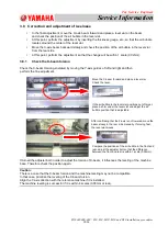
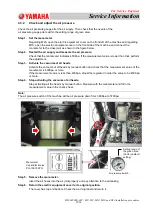
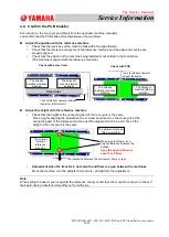
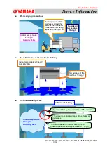
In the final adjustment, move the X-axis beam forward and place a level vial on the beam
and check the position of the air bubble in the level vial.
At this point, perform the adjustment by inserting the thickness gauge, etc., so that the air bubble
locates around the center of the level vial.
Move the X-axis beam backward slowly and check the position of the air bubble in the level vial
from the rear side.
At this point, perform the adjustment so that the change will be within 1 scale (0.02mm).
3.8.1
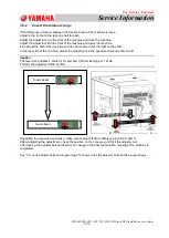
Check the X-beam torsion
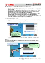
Check the X-beam torsion generated by moving the Y-axis guides of left and right and then
perform the fine adjustment.
If turned the adjuster bolt in order to adjust the torsion of X-beam, it influences the leveling of the machine
base. Therefore check the position again.
Caution:
There is a case that the X-beam torsion and the machine leveling may not be compatible.
In that case, prioritize the leveling of the X-beam torsion.
Align the Y-axis direction with the reference machine if it is installed.
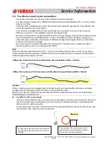
The machine leveling is successful if it is within 4 scales (0.08mm or less).
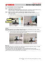
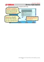
After confirming that the Z-axis is not lowered, move the
beam slowly to the rear side manually. If moving fast,
the level vial moves.
Compare the positions of the air bubble in the front and
rear, adjust the adjuster bolt so that the difference
between the front and rear is within 1 scale (0.02mm).
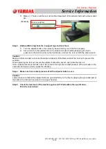
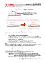
Move the X-beam forward and place a level vial.
Check the level.
If the air bubble in the level vial positions out of target,
place a shim under the level vial and adjust the air
bubble position that is adjustable.

