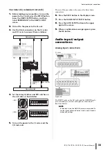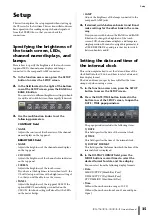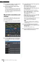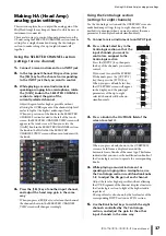
background image

Using libraries

 Owner’s Manual

23

Using libraries

This section explains basic operations for libraries. 
Libraries allow you to store and recall settings for the 
currently-selected channel (EQ/dynamics) or rack 
(GEQ/effect/Premium Rack).
The following libraries are provided.

Input channel library

Output channel library

Input EQ library

Output EQ library

Dynamics library

GEQ library

Effect library

Dante input patch library

Premium Rack library

The method of operation is essentially the same for each 
library.

NOTE

Premium Rack library features a library for each Premium 
Rack type.

Recalling settings from a library

1.

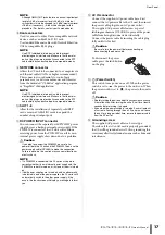
Open a popup window that provides the tool 
buttons.

To access each popup window, proceed as follows. To 
recall settings from a channel library, first display the 
SELECTED CHANNEL VIEW screen. Then, proceed 
to Step 3.

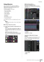
[SELECTED CHANNEL VIEW screen]

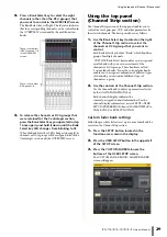
Press one of the knobs in the SELECTED CHANNEL 
section to access the SELECTED CHANNEL VIEW 
screen.

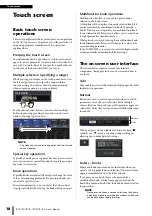
[HPF/EQ popup window]
[Dynamics 1/2 popup window]

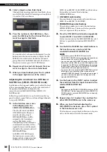
In the SELECTED CHANNEL VIEW screen or the 
OVERVIEW screen, press the appropriate field for EQ 
or Dynamics 1/2.

1

 EQ field

2

 Dynamics 1/2 field

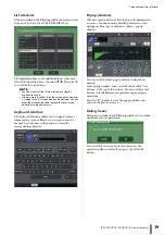
[GEQ/EFFECT/PREMIUM RACK popup 
window]

In the VIRTUAL RACK window that appears when 
you press the RACK button in the function access 
area, press a rack in which a GEQ/effect/Premium 
Rack is already mounted.

1

 RACK button

2

 Racks

2

1

1

2

1

2

Содержание CL3

Страница 1: ...EN Owner s Manual Keep This Manual For Future Reference...

Страница 2: ...ption card 34 Setup 35 Specifying the brightness of the touch screen LEDs channel name displays and lamps 35 Setting the date and time of the internal clock 35 Word clock connections and settings 36 M...

Страница 3: ...two blades and a third grounding prong The wide blade or the third prong are provided for your safety If the pro vided plug does not fit into your outlet consult an electrician for replacement of the...

Страница 4: ...is coloured GREEN and YELLOW must be connected to the terminal in the plug which is marked by the letter E or by the safety earth symbol or colored GREEN or GREEN and YELLOW The wire which is coloure...

Страница 5: ...thers or damage to the device or other property These precautions include but are not limited to the following When removing the electric plug from the device or an outlet always hold the plug itself...

Страница 6: ...e content created with this product in revenue generating broadcast systems terrestrial satellite cable and or other distribution channels streaming applications via Internet intranets and or other ne...

Страница 7: ...re are available on the following website http www yamahaproaudio com For information about updating and setting up the unit please refer to the firmware update guide available on the website About th...

Страница 8: ...etworks If multiple CL units share the same I O rack the gain compensation function will maintain network audio streams at a constant level to help you enjoy the benefits of a large scale sound system...

Страница 9: ...for the administrator and for users to help prevent important settings from being changed accidentally Information specific to each user user level system settings and user defined key knob settings c...

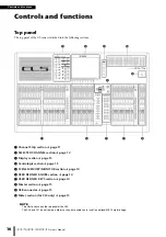
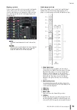
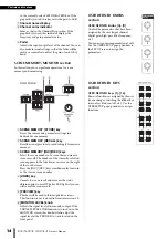
Страница 10: ...ection page 13 4 Centralogic section page 13 5 SCENE MEMORY MONITOR section page 14 6 USER DEFINED KNOBS section page 14 7 USER DEFINED KEYS section page 14 8 Master section page 15 9 USB connector pa...

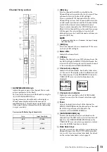
Страница 11: ...be cue monitored If the cue is on the key LED will light 4 Meter LEDs Indicate the channel level 5 ON key Switches the channel on or off If a channel is on the key LED will light In SENDS ON FADER mod...

Страница 12: ...and 18 dB Keep in mind that noise may be generated when using phantom power if there is a difference between the Hot and Cold output impedance of an external device connected to the INPUT connector T...

Страница 13: ...s DCA groups or custom groups selected by the Bank Select keys 1 Bank Select keys Select a bank to be controlled in the Centralogic section Press the INPUT key then press one of the Bank Select keys b...

Страница 14: ...unction access area on the right of the touch screen Press the INC DEC keys simultaneously to return to the current scene number 4 UNDO key Cancels the scene recall and recovers the status obtained pr...

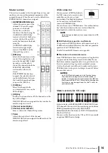
Страница 15: ...e to the USB connector to record or play audio files and to save or load internal data The Help file displayed on the unit screen is loaded from a connected USB flash drive You can also save on a USB...

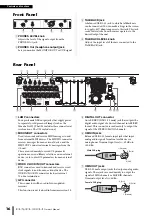
Страница 16: ...es from the CL unit These are used mainly to record CL parameter operations or scene library selections on an external device or to control CL parameters from an external device 3 WORD CLOCK IN OUT co...

Страница 17: ...off both the CL unit and the PW800W Then use the power supply cable PSL360 to make the connection Failure to observe this caution may cause malfunction or electric shock NOTE If a PW800W is connected...

Страница 18: ...are used to operate knobs selected in the touch screen A thick line will be displayed around a selected knob if it can be controlled by a multifunction knob Typically a knob of this type corresponds...

Страница 19: ...a name or comment to a scene or library or to assign a name to a channel Press the keys in the window to enter the corresponding character Popup windows When you press a button or field for a specific...

Страница 20: ...ess this button to switch to CH JOB mode where you can make settings for channel grouping and linking During this time the function access area of the touch screen will switch to a screen that enables...

Страница 21: ...el and DCA group and assign a title to scene and library data when saving it To assign a name you will use the keyboard window shown in the main area 1 Access the screen for assigning a name The scree...

Страница 22: ...l buttons In some popup windows the title bar at the top of the window contains tool buttons for additional functions You can use these buttons to access related libraries or to copy parameters from o...

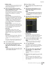
Страница 23: ...settings from a library 1 Open a popup window that provides the tool buttons To access each popup window proceed as follows To recall settings from a channel library first display the SELECTED CHANNEL...

Страница 24: ...e recalled to all the selected channels GEQ EFFECT PREMIUM RACK popup window Use the rack select tabs at the bottom of the popup window to select a rack NOTE You cannot select a rack select tab of a r...

Страница 25: ...not be possible to press the RECALL button 5 Press the RECALL button 6 The selected data will immediately be loaded into the channel EQ dynamics or rack GEQ effect Premium Rack you selected in step 2...

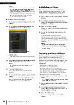
Страница 26: ...ect the channel EQ dynamics or rack effect Premium Rack for which you want to initialize the settings 3 Press the DEFAULT button A dialog box will ask you to confirm the initialization operation 4 To...

Страница 27: ...en a popup window that provides the tool buttons 2 Select a channel EQ dynamics or rack GEQ effect Premium Rack 3 Press the COPY button to place the current settings in the buffer memory This will be...

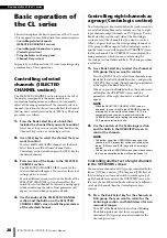
Страница 28: ...r DCA groups Use the Bank Select keys on the right side of the Centralogic section to select the channels that you want to control When you press the keys the corresponding channels or DCA groups will...

Страница 29: ...groups that you want to control Each Bank Select key holds a Bank which bundles a group of multiple channels CUSTOM Bank Select keys enable you to assign and recall a bank with your own assortment of...

Страница 30: ...X and the buttons that enable you to select the destination MIX MATRIX buses 1 ON FADER switch button Pressing this button repeatedly will switch between MIX1 16 and MIX17 24 MATRIX 2 MIX MATRIX bus s...

Страница 31: ...the network Visit the Audinate website for more details on Dante http www audinate com Additional information on Dante is also posted on the Yamaha Pro Audio website http www yamahaproaudio com About...

Страница 32: ...ctions turn on the power to the CL unit press the SETUP button press the DANTE SETUP button and then select DAISY CHAIN in the DANTE SETUP screen 2 Turn off the power to the CL unit 3 Use the Dante co...

Страница 33: ...creen 7 Press the DANTE INPUT PATCH button 8 Press the AUTO SETUP button in the upper right of the screen 9 When a confirmation message appears press the OK button Audio input output connections Analo...

Страница 34: ...t speaker processor units Refer to the Yamaha professional audio website for the most recent information on available I O cards http www yamahaproaudio com Installing an option card Before you install...

Страница 35: ...r bridge is installed on the CL3 CL1 this knob setting will also affect the LEDs on the meter bridge LAMP Adjusts the brightness of the lamps connected to the rear panel LAMP jacks 4 If desired switch...

Страница 36: ...SELECT field select the desired clock source When using the internal word clock Press the INT 48k or INT 44 1k button When a device on the Dante network serves as the clock master Press the DANTE 48k...

Страница 37: ...screen will change accordingly Using the Centralogic section settings for eight channels Use the Centralogic section and the OVERVIEW screen to make head amp settings for up to eight channels This me...

Страница 38: ...black characters on gray background press the button to switch it on 4 Verify that in the top panel the ON key of the corresponding input channel is turned on If the ON key is off the LED is dark pres...

Страница 39: ...TO ST PAN BALANCE field of the SELECTED CHANNEL VIEW page to display a popup window then switch the status on 3 In the Centralogic section verify that the ON key of the corresponding input channel is...

Страница 40: ...Turn on the power to the CL series the I O rack and then amplifier in this order 4 Press the RACK button in the display screen then press the I O RACK tab 5 Confirm that the I O rack is recognized cor...

Страница 41: ...he Channel Strip section or Centralogic section 2 Press the GAIN knob in the SELECTED CHANNEL section 3 Press the 48V button in the GAIN PATCH popup window as necessary depending on the microphone you...

Страница 42: ...Edit the dynamics type and parameters in the DYNAMICS popup window Use the knobs in the Centralogic section to edit the parameters 5 Edit the DYNAMICS 2 parameters in the same way Setting the output c...

Страница 43: ...alogic section s faders 9 Perform the same operations for other GEQs as desired NOTE The graphic EQ in the GEQ rack can be used only for the output channels If you wish to use GEQ for the input channe...

Страница 44: ...press the OUTPUT key then ST IN key 14 Adjust the effect return level using the fader in the Centralogic section 15 If necessary press the RACK button then the effect track icon of the EFFECT tab and...

Страница 45: ...RACK 11 Adjust the parameters in the PREMIUM RACK popup window Changing the patch settings Setting up INSERT or DIRECT OUT 1 Select the bank that contains the channel for which you want to set up INSE...

Страница 46: ...contains the channels you want to link in the Channel Strip section or Centralogic section 4 While pressing and holding down the SEL key of one channel press the SEL key of the other channel that you...

Страница 47: ...field press the channel strip number button 6 Press the SEL key for the channel that you want to assign in the Channel Strip section 7 In the same way select other channels that you want to assign Usi...

Страница 48: ...ious screen then press the OUTPUT button in the OSCILLATOR area Using scene memories Storing a scene 1 Use the INC DEC keys in the SCENE MEMORY section to select the store destination scene number 2 P...

Страница 49: ...5 Press the Rec button to arm recording 6 Press the Play button to start recording 7 When you have finished recording press the Stop button Playing audio files from a USB flash drive 1 Connect a USB f...

Страница 50: ...a name and comments then press the SAVE button Loading the unit settings from a USB flash drive 1 Press the SETUP button in the display screen 2 Press the SAVE LOAD button 3 To select the file that yo...

Страница 51: ...ge indicates that the initialization process is complete Press the EXIT button The CL will start up in normal operating mode NOTE Alternatively you can continue the operation by selecting a different...

Страница 52: ...s that you want to calibrate Faders for which a problem was detected at start up will already be selected 4 Press the START button A confirmation dialog box will appear 5 Press the OK button in the di...

Страница 53: ...or digital gain on the head amplifier exter nal head amp device or I O rack set to an appropriate level Are the input channel faders raised Could the EQ gain be turned down excessively Are EQ s attenu...

Страница 54: ...a way that the channels or parameters will not be updated Could user level restrictions have been specified You turn on a CUE button in the EFFECT screen but it is automatically defeated This is defe...

Страница 55: ...s 48kHz Fader 100mm motorized Resolution 1024steps 10dB to 138dB dB all faders Frequency Response 0 5 1 5dB 20Hz 20kHz refer to 4dBu output 1kHz OMNI IN to OMNI OUT Total Harmonic Distortion 4 Less th...

Страница 56: ...t current Imax 300mA 2 4pin 12V 3pin GND Lamp rating 5W Voltage control by software Input Terminals GAIN Actual Load Impedance For Use With Nominal Input Level Connector Sensitivity 1 Nominal Max befo...

Страница 57: ...8 24V 20 CAUTION 9 24V 21 DETECT A 10 GND 22 DETECT B 11 GND 23 DETECT GND 12 GND Frame GND 1 2 3 4 5 6 7 8 9 10 11 12 13 14 15 16 17 18 19 20 21 22 23 Pin Signal Name Pin Signal Name 1 GPO1 9 GPO2 2...

Страница 58: ...Dimensions Owner s Manual 58 Dimensions 1053 15 201 130 299 667 CL5 CL3 CL1 648 15 201 130 299 667 839 15 201 130 299 667 Unit mm...

Страница 59: ...inking 46 List windows 19 Llibraries 23 M Main area 21 MIX MATRIX bus 30 Multifunction knob 18 MUTE group 46 N Name displays 35 Network connections 31 O Option card 34 Oscillator 48 P Patch 45 Phantom...

Страница 60: ......
Страница 61: ...PRE FADER PFL POST ON AFL POST PAN R EFFECT CUE SELECT PFX1 8 OUT L R EFFECT CUE ON KEYIN CH1 72 KEYIN CUE KEYIN CUE SELECT ON ON POST ON METER POST ON MIX OUT1 24 INSERT METER PRE FADER PRE FADER INS...

Страница 62: ...NITOR L MONITOR R MONITOR MONO C MONITOR OUT MONO C MONITOR OUT R MONITOR OUT L To OUTPUT PATCH To OUTPUT PATCH To OUTPUT PATCH MONO METER MONITOR R METER MONITOR MONO C TALKBACK ON METER MONITOR L CU...

Страница 63: ...g 20 10 0 10 20 30 40 50 60 70 80 90 100 110 120 130 140 150 160 24 4 170 180 190 Nominal Output 24dBu 4dBu 30 30 OMNI OUT1 8 Default setting Nominal Output 75mW 8 150mW 8 Max Output PHONES OMNI IN 1...

Страница 64: ...ic Europe GmbH Branch Italy Viale Italia 88 20020 Lainate Milano Italy Tel 02 935 771 SPAIN PORTUGAL Yamaha Music Europe GmbH Ib rica Sucursal en Espa a Ctra de la Coruna km 17 200 28230 Las Rozas Mad...

Страница 65: ...204IPTO A0 2012 Yamaha Corporation C S G Pro Audio Division Printed in Japan ZC58320 Yamaha Manual Library http www yamaha co jp manual Yamaha Pro Audio Global Web Site http www yamahaproaudio com...

Отзывы: