background image

Using the internal hard disk/external storage devices

166

Chapter

11

Operation section

Tidying up the data of the internal hard disk 

(Defrag)

The Defrag operation re-orders the data on the inter-
nal hard disk so that each piece of data is located in 
physically consecutive areas on the hard disk.
When you record immediately after formatting the 
internal hard disk, the audio data will be written on 
physically consecutive areas of the hard disk. How-
ever as you continue to record and edit the data, sin-
gle items of continuous audio data may be written to 
separate locations that are distributed across the hard 
disk. (Such a state is referred to as “fragmentation.”) If 
fragmentation becomes severe, the access time will 
be degraded, causing the audio to “skip” during play-
back, or it may become impossible to create a new 
song even though there should be sufficient free space 
on the disk. You can resolve such problems by execut-
ing Defrag.

• In rare cases, data may be lost due to read/write 

errors during the Defrag operation. Important song 
data on the internal hard disk must be backed up 
before you use this operation.

• Execution of the Defrag operation will require 

approximately one hour per GB of data. The power 
of the AW2816 must not be turned off during this 
time. Doing so may irreparably damage the hard 
disk and/or data in a way that cannot be recovered. 
Do not use the Defrag operation if there is a possi-
bility of power failure due to lightning strikes or any 
other reason.

Tip!

You can produce essentially the same results as the 
Defrag operation by backing up all your songs, for-
matting the internal hard disk, and then restoring the 
songs. For details on backing up songs, refer to 
page 162.

1

Press the [FILE] key 

 [F3] key.

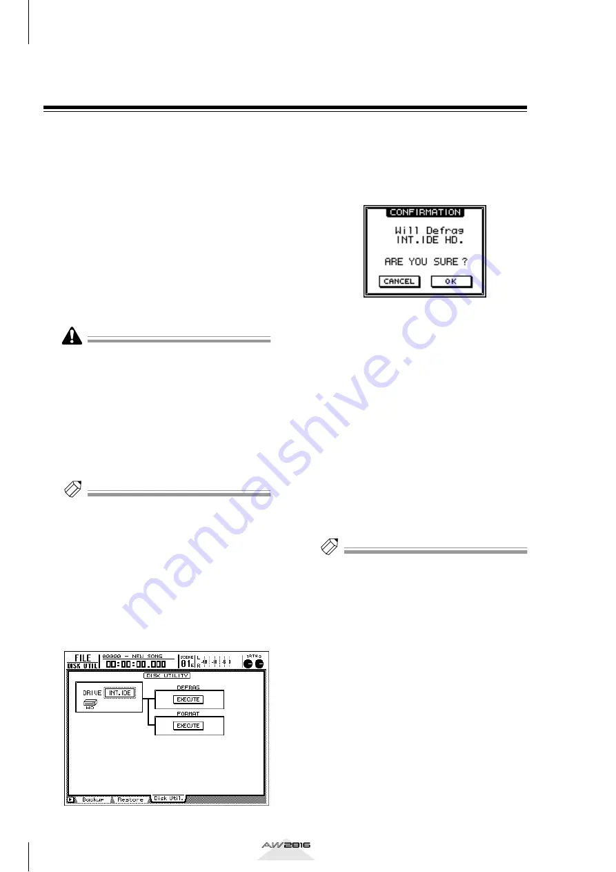
The FILE screen/Disk Util. page will appear.

2

Turn the [DATA/JOG] dial to select 
“INT.IDE,” and press the [ENTER] key.

A display like the following will appear.

3

Move the cursor to the EXECUTE button in 
the DEFRAG area, and press the [ENTER] 
key.

A popup window will ask you to confirm that 
you want to execute the Defrag operation.

4

To execute Defrag, move the cursor to the 
OK button and press the [ENTER] key. To 
cancel without executing, move the cursor 
to the CANCEL button and press the 
[ENTER] key.

When you move the cursor to the OK button and 
press the [ENTER] key, the current song will be 
saved, and then the Defrag operation will begin. 
While Defrag is being executed, the state of 
progress and the estimated remaining time will 
be displayed in a popup window.

5

If you want to cancel Defrag processing 
before it is completed, press the [ENTER] 
key.

The process will be halted, and you will return to 
the display of step 2.

Tip!

• The time required for Defrag to be completed will 

depend on the structure of the song and on the 
arrangement of data. In some cases, processing may 
take less time than the remaining time displayed in 
the popup window.

• If the Defrag operation is not necessary, a message 

of “Defrag Cluster Not Found!” will be displayed 
when you execute step 4, and Defrag will not be 
executed.

• If an error in the song data is found while Defrag is 

being processed, that song will be skipped, and 
Defrag processing will continue. In this case, infor-
mation about the song in which the error was found 
will be displayed immediately after Defrag is com-
pleted.

• If a hard disk read/write error occurs during Defrag 

processing, the contents of the error will be dis-
played, and Defrag will be halted.

Содержание AW2816

Страница 1: ...PROFESSIONAL AUDIO WORKSTATION PROFESSIONAL AUDIO WORKSTATION E Owner s Manual Owner s Manual Keep This Manual For Future Reference Keep This Manual For Future Reference ...

Страница 2: ...a Park CA 90620 The above statements apply ONLY to those products distributed by Yamaha Corporation of America or its subsidiaries WARNING THIS APPARATUS MUST BE EARTHED IMPORTANT THE WIRES IN THIS MAINS LEAD ARE COLOURED IN ACCORDANCE WITH THE FOLLOWING CODE GREEN AND YELLOW EARTH BLUE NEUTRAL BROWN LIVE As the colours of the wires in the mains lead of this apparatus may not correspond with the c...

Страница 3: ...e Afdeiing Kanaalweg 18 G 3526 KL UTRECHT Tel 030 2828425 Gooi de batterij niet weg maar lever hem in als KCA This apparatus contains a lithium battery for memory back up For the removal of the battery at the moment of the disposal at the end of the service life please consult your retailer or Yamaha Service Center as follows Yamaha Music Nederland Service Center Address Kanaalweg 18 G 3526 KL UTR...

Страница 4: ...e con nectors on the unit Otherwise malfunction fire or electrical shock may result If lightning begins to occur turn off the power switch of the unit as soon as possible and unplug the power cable plug from the electrical outlet If there is a possibility of lightning do not touch the power cable plug if it is still connected Doing so may be an electrical shock hazard Cautions This unit has ventil...

Страница 5: ...s equipment Take extreme care to avoid touching any terminals or board surface parts In order to protect the electronic circuits of the I O card hard disk CD RW drive etc from damage due to static electricity when handling any of this equipment take the most extreme care to avoid touching IC leads or other electronic parts Be careful not to drop any screws into the main unit If you switch the powe...

Страница 6: ...cific area Manual Punch in out 63 Automatically re recording only a specific area Auto Punch in out 64 Switching virtual tracks 66 Operating multiple faders together Fader Groups 67 Operating multiple ON keys together Mute Groups 68 Using the Solo function 69 Chapter4 Input output patching71 Assigning signals to input channels return channels Input Patch 71 Assigning signals to the recorder inputs...

Страница 7: ...CD Play 177 Chapter12 Mastering 179 About mastering 179 Stereo tracks that can be mastered 179 Media that can be used with the CD RW drive 179 Track At Once and Disc At Once 180 Checking the free space on the internal hard disk 181 Setting the mastering mode 181 Executing mastering 182 Finalizing a disc 185 Chapter13 MIDI 187 What you can do using MIDI 187 MIDI connectors and the TO HOST connector...

Страница 8: ...6 EQ Att page 296 Library page 298 Fader Grp page 300 Mute Grp page 301 DYN DLY screen 302 Dyn Edit page 302 Library page 304 Dly ø1 8 Dly øMONI page 306 AUX1 AUX4 screens 307 Pre Pst page 307 AUX5 EFF1 AUX6 EFF2 screens 309 Eff Edit page 309 Library page 311 Pre Pst page 313 REMOTE screen 314 Remote A Remote D pages 314 HOME screen 318 IN Rtn MONI page 318 Bus page 319 Omni ST page 320 Option pag...

Страница 9: ... 377 Preset Dynamics Program Parameters 382 Troubleshooting 388 Display message list 392 Messages 392 Popup messages 394 Messages at power on 395 Specifications 396 General Specifications 396 Mixer section 397 Recorder section 399 Controls 400 Control I O 400 Dimensions 401 MIDI data format 402 MIDI Implementation Chart 414 Index 415 Block diagram Appendix Index ...

Страница 10: ...oduced or distributed in any form or by any means without the prior written authorization of Yamaha Corporation 2000 Yamaha Corporation All rights reserved Trademarks ADAT MultiChannel Optical Digital Interface is a trademark and ADAT and Alesis are registered trade marks of Alesis Corporation Apple and Macintosh are registered trademarks of Apple Computer Inc Tascam Digital Interface is a tradema...

Страница 11: ...bility for any damages neither direct nor indirect resulting from the use of any of the above hard disks Installation Please read and observe the cautions on installing optional equipment listed at the beginning of this manual The following steps describe the procedure by which the 2 5 inch IDE hard disk is attached to the hard disk cover plate located on the bottom of the AW2816 for installation ...

Страница 12: ... cable from inside the AW2816 and plug the flat cable into the connector of the hard disk as shown in the illustration Press both ends of the flat cable connector to ensure that it is firmly plugged in all the way Even if the connector is difficult to insert do not attempt to insert it by applying excessive force Doing so may damage the hard disk or you may injure yourself When inserting the conne...

Страница 13: ...the AW2816 and successfully tested by means of various operational tests However we cannot take into account slight differences in performance that may occur due to the manufacturing tolerances of each manufacturer Please be aware that Yamaha Corporation will accept no responsibility for any damages neither direct nor indirect resulting from the use of any of the above CD RW drives CD RW drive set...

Страница 14: ... outlet Always switch off the power for the main unit and all peripherals unplug the power cord for the main unit from the outlet then disconnect the cables connect ing the main unit with the peripherals before starting installation work 3 Spread a soft cloth over your work surface and place magazines or books to support the four corners of the AW2816 so that the faders keys and other controllers ...

Страница 15: ...with the screw holes in the AW2816 and using a screw driver and the included screws fasten it in four locations 8 Re attach the CD RW drive cover and the bottom panel that you removed in step 4 At this time remove the inner cover from the CD RW drive cover CD R RW drive cover panel Inner cover Bottom panel ...

Страница 16: ...ency disc removal Manual eject allows you to remove the disc manually in the case of an emergency such as a malfunction of the disc tray mechanism usually temporary or a power failure Please be aware that using this method frequently can cause the CD RW drive to malfunc tion For the location of the eject hole and the proce dure refer to the manual of your CD RW drive In order to perform this opera...

Страница 17: ...tion will accept no responsibility for any damages neither direct nor indirect resulting from the use of any of the above storage devices It is not possible to directly record or play back audio signals in realtime on an external storage device con nected to the SCSI connector Connection procedure 1 Make sure that the power is turned off for the AW2816 and for the external SCSI device s and use a ...

Страница 18: ...annot be defeated About SCSI errors The SCSI bus is able to transfer data in a stable man ner only if all connected SCSI devices are operating correctly If the SCSI bus of the AW2816 is connected to a device whose operation is unstable or which pro duces noise errors may occur in other devices or the AW2816 may fail to start up correctly If such prob lems occur check the following points Check the...

Страница 19: ...jacks MY4 DA This is a D A card with four channels of analog out put jacks balanced XLR jacks For up to date information on available MY cards contact your local Yamaha distributor or check the fol lowing website http www aw2816 com Installation procedure Please carefully read the cautions for installing optional devices given at the beginning of this man ual 1 Make sure that the power of the AW28...

Страница 20: ...ed automatically and the screen shown above will appear when formatting has been com pleted Never turn off the power of the AW2816 while for matting is in progress Doing so may damage the hard disk itself Setting the internal clock When the AW2816 is shipped from the factory the internal clock is set to Japan time When you save a song you created on the AW2816 the date and time will be stored acco...

Страница 21: ...GATE section located on the top panel of the AW2816 press the SONG key 2 Press the F5 SHUT DOWN key located below the display 3 Press the ENTER key A message will ask you whether you want to save the current song 4 Use the CURSOR keys located in the right center of the top panel to move the cursor to the OK button and press the ENTER key 5 When a message of Now safe to turn off appears turn off th...

Страница 22: ...ut sensitivity of INPUT jacks 1 8 over a range of 4 dB to 46 dB They support signals ranging from line level devices such as synthesizers to mic inputs B PEAK indicators A PEAK indicator will light red if the input signal that has passed through the GAIN control reaches a level 3 dB below the clipping point In order to record at the optimal level adjust the GAIN control 1 so that this indicator fl...

Страница 23: ...he UTILITY screen where you can operate the test tone oscillator and make set tings for the operating environment of the AW2816 C MID key This key accesses the MIDI screen where you can make MIDI related settings D PATCH key This key accesses the PATCH screen where you can patch external inputs outputs to internal signal routes MIXER section A VIEW key This key accesses theVIEW screen where you ca...

Страница 24: ...y is on you can use faders 1 8 to control the send levels of the signals sent to AUX buses 1 4 from the channels selected in the MIX ING LAYER section The display will show the AUX 1 AUX 4 screens where you can make on off and pre post settings for the signals sent from each channel to AUX 1 4 D REMOTE key When this key is on you can use faders 1 8 and ON keys 1 8 to remotely control external MIDI...

Страница 25: ...ng faders adjust either the input level of each channel or the send level of each channel to AUX buses 1 6 D RTN 1 RTN 2 controls According to the settings of the FADER MODE section these knobs adjust either the level of return channels 1 2 effect return or the send level from return channels 1 2 to AUX buses 1 6 Return channel 1 does not have a send level to AUX bus 5 Similarly return channel 2 d...

Страница 26: ... C F1 F5 Function 1 5 keys These keys select pages within the currently selected screen When the SHIFT key or CTRL key is held down these keys execute additional functions assigned to each key D CTRL Control key This key is used in conjunction with the function keys 3 to execute user defined functions E Contrast This knob adjusts the brightness of the display F Access indicator This indicator indi...

Страница 27: ... output channel C REC TRACK SELECT 1 16 ST These keys select the recording track tracks 1 16 or the stereo track D ALL SAFE key This key cancels record ready mode for all tracks If any tracks are muted all muting will be can celled RECORDER section A TRACK key This key accesses the TRACK screen where you can operate the audio tracks of the recorder sec tion B EDIT key This key accesses the EDIT sc...

Страница 28: ...s the scene number currently shown in the display CURSOR JOG SHUTTLE section A JOG ON key This key is an on off switch for the Nudge function a destination that repeatedly plays a specified region before or after the current location con trolled by the DATA JOG SHUTTLE dial When the Nudge function is on the JOG ON key will light B DATA JOG dial Depending on the on off status of the JOG ON key and ...

Страница 29: ...nt at which recording most recently began In point or ended Out point F SET key This key is used in conjunction with the LAST REC IN OUT keys or the A B keys to set the cur rent location of the song to a locate point G REPEAT key This key is an on off switch for the A B Repeat function which repeatedly plays a specified region H A B keys These keys set the beginning A point and end B point of the ...

Страница 30: ...he STOP key or PLAY key C STOP key This key stops playback recording fast forward or rewind D PLAY key When the recorder is stopped pressing this key will begin playback If you hold down the REC key and press this key recording will begin Pressing this key during rewind or fast forward will switch to normal speed playback Pressing this key during recording will stop record ing and continue pressin...

Страница 31: ...ake priority Phantom power is not supplied from the INPUT 1 2 TRS phone jack D INPUT 3 8 TRS phone jacks These are balanced TRS phone input jacks The specifications of these jacks are the same as for the INPUT 1 2 phone jacks E INPUT 8 Hi Z jack This is a high impedance unbalanced phone input jack Instruments with a high output impedance such as passive type electric guitars can be con nected dire...

Страница 32: ...t can be connected directly to the serial port of a PC or Macintosh for use with MIDI application pro grams O FOOT SW jack An optional foot switch Yamaha FC5 can be con nected to this jack You can use the foot switch to perform transport operations such as playback stop and to control manual punch in out Foot switches other than the Yamaha FC5 or equiva lent may not operate correctly P MIDI IN con...

Страница 33: ... and their functions 24 Chapter 1 Operation section Front panel A CD RW drive cover This covers the installation bay for the optional CD RW drive Tip For details on installing a CD RW drive refer to page 4 1 ...

Страница 34: ... for each song The AW2816 also provides various libraries in which EQ dynamics processor channel and patching settings can be stored independently Full automated mixing The AW2816 features nine 60 mm motor drive fad ers Fully automated mixing allows time axis recording of not only scene memory and library recall operations but also fader movements pan operations and EQ operations Recorder section ...

Страница 35: ...d analog are sup ported The AW2816 s open architecture ensures excellent expandability Import export audio data WAV files can be loaded from CD ROM or MO disk and audio from tracks recorded on the AW2816 can be converted and written as a WAV file This allows audio files to be exchanged with waveform editing software running on your com puter Track audio data and some song data is com patible with ...

Страница 36: ...ITAL STEREO IN Input signal from the DIGITAL STEREO IN jack METRONOME Playback sound of the internal metronome The following input signals can be assigned to each channel Input channels 1 8 Monitor channels 1 16 Return channels 1 2 Buses 1 8 AUX buses 1 6 STEREO bus SOLO bus Channel insert I O OPTION I O slot Mixer section AW2816 Recorder section Internal effects CD RW drive 8 2 2 2 2 2 8 CD Write...

Страница 37: ...m to be sent directly from various output jacks or to the recorder section 48V SLOT IN 8 2 EFFECT1 EFFECT2 2 DIGITAL STEREO IN 2 Hi z INPUT 8 ONLY METRONOME INPUT PATCH MIC LINE INPUT OPTION I O SLOT AD INPUT 1 2 INPUT 3 8 PEAK PEAK INPUT1 24 PHANTOM LINE MIC LINE MIC COAXIAL AD INPUT1 24 SELECTED INSERT RETURNS 30 INPUT 1 8 BUS 1 BUS 2 BUS 3 BUS 4 BUS 5 BUS 6 BUS 7 BUS 8 STEREO L STEREO R SOLO L ...

Страница 38: ...ignal returned from an internal effect to a return channel will not be sent to the same effect producing a loop Even if other input signals are assigned to return channels 1 2 the send level to the corresponding AUX bus will not be available Recorder input patch This section assigns input signals to the tracks of the recorder The following signals can be selected for tracks 1 16 BUS 1 8 The output...

Страница 39: ...patch section and patched to an input channel This is convenient when you want to link an external digital mixer or similar device with the mixer section of the AW2816 Cascade connection settings are made in the SETUP screen D in Setup page Oscillator The AW2816 contains an oscillator that allows you to select either sine wave 100 Hz 1 kHz 10 kHz or white noise The oscillator signal can be sent to...

Страница 40: ...nd are sent to the output patch section The master level of buses 1 8 is con trolled in the HOME screen Bus page AUX buses 1 6 The signals sent from each channel to AUX buses 1 6 pass through a master level and are sent to the output patch section The master level of AUX buses 1 6 is controlled in the HOME screen Bus page Tip With the AW2816 s default settings the output of AUX buses 5 6 is sent t...

Страница 41: ...llows depending on the state of the AW2816 1 When the AW2816 is in the default state The signal of the stereo output channel will be out put directly to the MONITOR OUT jacks PHONES jack B When the SOLO key is on The signal of the channel selected by the ON key will be sent to the SOLO bus and will be output from the MONITOR OUT jacks PHONES jack During this time other signals will be muted C When...

Страница 42: ... defeat track muting To defeat muting you must access the METER screen P 351 and turn off muting for each track or use the ALL SAFE key If you use the ALL SAFE key muting and record ready mode will be defeated simultaneously for all tracks Virtual tracks These are virtual tracks that can be selected On the AW2816 one virtual track 1 8 can be selected for each audio track 1 16 and used for recordin...

Страница 43: ...s is the scene number of the currently selected scene the current scene If the mix parameters of the last stored recalled scene have been edited an E symbol will be displayed at the lower right F Level meters L R These level meters show the output level of the stereo output channel the signal after passing through EQ and the dynamics processor G RTN 1 2 knobs These knobs indicate the input levels ...

Страница 44: ...rs numerical boxes in the display are used to edit the value of the corresponding parameter The value of a knob or fader is displayed below or at the right of it Tabs If a screen contains multiple pages the name of each page will appear at the bottom of the display The area in which each name is displayed is called a tab Tabs are used to switch between pages within a screen For some screens additi...

Страница 45: ...will appear 2 To select another page within that screen press the function key F1 F5 that cor responds to the desired page The tabs displayed at the bottom of the screen correspond to the function keys F1 F5 as shown in the following illustration For example if you want to access the Patch OUT page of the PATCH screen press the F2 key Tip You can also move successively between the pages of a scree...

Страница 46: ...appear allowing you to assign a name to the scene or library When you create a new song a NAME EDIT popup window will appear allowing you to assign a name to the song The popup window contains the following areas and functions 1 Text input box Characters numerals and symbols you input are displayed in this box When you store a library or scene for the first time a default name will be dis played h...

Страница 47: ...nd the previous screen will reappear A scene or library can be given a name of up to 16 characters and a song name and comment can be up to 64 characters long Selecting a channel In order to operate the mix parameters of a channel on the AW2816 you must first select the channel that you want to operate Here s how to select a channel 1 Use the keys of the MIXING LAYER section to select the mixing l...

Страница 48: ...els 9 16 to AUX bus 2 AUX 3 Send levels from input channels 1 8 to AUX bus 3 Send levels from monitor channels 1 8 to AUX bus 3 Send levels from monitor channels 9 16 to AUX bus 3 AUX 4 Send levels from input channels 1 8 to AUX bus 4 Send levels from monitor channels 1 8 to AUX bus 4 Send levels from monitor channels 9 16 to AUX bus 4 AUX 5 Send levels from input channels 1 8 to AUX bus 5 effect ...

Страница 49: ...up This section explains connections to external devices creating a new song word clock settings and other things that you need to do before you begin record ing Making connections The following diagram shows common examples of audio signal connections Refer to this diagram and connect the mics instruments or external devices that you will use MONITOR system Headphones MONITOR OUT INPUT 1 2 3 8 IN...

Страница 50: ... to the AW2816 the AW2816 itself your monitor sys tem When you turn on the power of the AW2816 the song that was used most recently will be loaded automatically If SCSI devices are connected to the AW2816 the AW2816 may not start up correctly if its power is turned on when the connected SCSI devices are still powered off SCSI devices must be turned on before the AW2816 2 Press the SONG key F1 key ...

Страница 51: ...ly created song For this example you do not need to make any selection here Tip If you select 48 kHz as the sampling frequency a popup window will appear following step 5 inform ing you that it will not be possible to create a CD from this song Move the cursor to the OK button and press the ENTER key Mixer data can be imported even after a new song is created P 155 7 Move the cursor to the OK butt...

Страница 52: ...t channels 1 2 7 8 from the digital I O card and the AW2816 will synchronize to the clock data included in that input signal D ST IN The clock data included in the input signal of the DIGITAL STEREO IN connector will be used as the word clock source INT Use the internal clock of the AW2816 A button will be highlighted to indicate that it has been selected as the current word clock source An X supe...

Страница 53: ...s sampling frequency field in the upper left of the display If you are using the internal clock of the AW2816 as the clock source the sampling frequency selected when you created the current song will be the sam pling frequency of the entire system If you want the AW2816 to follow an external clock source you must make sure that the sampling fre quency of the song matches the value displayed in th...

Страница 54: ...s page displays meters that show the input levels of the input channels return chan nels and monitor channels 3 In the MIXING LAYER section press the INPUT 1 8 key to select input channels 1 8 as the mixing layer The INPUT 1 8 key will light and now you can use SEL keys 1 8 ON keys 1 8 and faders 1 8 to control input channels 1 8 Tip Mixing layer refers to the group of channels that is being contr...

Страница 55: ...t channels 1 To assign input channels 1 2 as a stereo pair hold down SEL key 1 and press SEL key 2 When you simultaneously press two adjacent odd numbered even numbered SEL keys a CHANNEL PAIRING popup window will appear allowing you to specify how pairing will occur 2 Move the cursor to one of the following buttons INPUT x y x odd number y even number The parameters of the odd numbered channel wi...

Страница 56: ...and assign it to buses 2 Move the cursor to the ST button of input channel 1 and press the ENTER key to turn it off Now the input signal of input channels 1 2 will no longer be sent to the stereo bus In this exam ple input channels 1 2 have been paired so that when you operated the ST button of input chan nel 1 input channel 2 followed the setting Tip When the AW2816 is in the default state input ...

Страница 57: ...ER key The functions of the meter area are the same for both pages 7 In the INPUT MONITOR area make sure that the AUTO button is on The three buttons in the INPUT MONITOR area located in the lower right of the METER screen are used to select the input metering mode the way in which input metering of each track is switched When the AUTO button is on the sig nal being monitored for record ready trac...

Страница 58: ...nal of the rhythm machine drum record ing mics will be sent via monitor channels 1 2 to the stereo bus 5 Move the cursor to the PAN knob of moni tor channel 1 and turn the DATA JOG dial to set the pan value to L16 far left In the same way set the PAN knob of mon itor channel 2 to R16 far right Tip Even when channels are paired the PAN knob phase and effect insert settings will not be linked 6 Make...

Страница 59: ...rforming on your instrument Tip When recording a live performance such as drums or guitar on the first track you may wish to monitor the click of the internal metronome as you record Metro nome operation is explained in chapter 14 Using the metronome P 229 5 When you are finished playing press the STOP key The REC key and PLAY key will go dark and recording will end 6 To hear the recorded content ...

Страница 60: ...ct input channels 1 8 as the mixing layer 4 Make sure that ON key 8 is turned on and raise fader 8 to the 0 dB position 5 While producing sound on your instru ment watch the level meters in the screen and check the input level of input channel 8 When the AW2816 is in the default state the input signal of INPUT jack 8 is patched to input channel 8 If the input channel 8 level meter reaches the OVER...

Страница 61: ... Press the PATCH key F1 key The PATCH screen Patch IN page will appear 5 Move the cursor to the RECORDER TRACK INPUT ASSIGN area and change the set ting of recorder input 3 to DIR 8 Now the input signal of input channel 8 bass will be sent directly to track 3 6 Press the REC TRACK SELECT 3 key The REC TRACK SELECT 3 key will begin blink ing and track 3 will be in record ready mode 7 Press the METE...

Страница 62: ...the input channel EQ to process the signal before it is recorded on the track 1 Press the INPUT 1 8 key SEL key 8 SEL key 8 will light and input channel 8 will be selected for operations 2 Press the EQ key F1 key The EQ screen EQ Att page will appear in which you can edit the EQ for input channel 8 3 Make sure that the ON OFF button in the upper left of the display is turned ON The ON OFF button s...

Страница 63: ... process only the signal being monitored without affecting the signal that is recorded on the recorder The EQ library special memory for storing EQ set tings contains preset EQ settings programs suit able for many types of instruments which you may find convenient to use Applying the dynamics proces sor to the input signal All channels of the AW2816 except for return chan nels 1 2 provide a dynami...

Страница 64: ...e you can press the ENTER key to switch the ON OFF button regardless of the loca tion of the cursor 8 While playing your instrument edit the dynamics processor parameters as desired To adjust the parameters move the cursor to the PARAMETER area in the lower right of the dis play and use the DATA JOG dial to edit the value The upper right of the display contains a meter that indicates the signal le...

Страница 65: ...d recording will stop 5 To listen to the recorded content press the key and then press the PLAY key If you decide to re do the recording stop the song press the UNDO key to cancel the previ ous recording and then repeat steps 1 4 Tip You can press the IN key of the Locate section to return instantly to the location at which recording was last begun 6 If you are satisfied with your recording press ...

Страница 66: ...f the stereo track is always patched to the output of the stereo output channel For this reason sending the signals of monitor channels 1 16 to the stereo bus allows them to be recorded via the stereo output channel onto the stereo track 4 Use the PAN knobs of monitor channels 1 16 to adjust the stereo position of each track 5 Raise the STEREO fader to the 0 dB posi tion Make sure that the ON keys...

Страница 67: ... effects 1 2 and the output of internal effects 1 2 is patched to the input of return channels 1 2 Thus if you are using the default settings it will not be necessary to change the patching 2 Press the PAN key F1 key The PAN ROUTE screen Pan 1 8 page will appear Make sure that in the RTN1 return channel 1 area the ST button is turned on and that the two PAN knobs are spread apart to left and right...

Страница 68: ...nt of audio tracks 1 16 and is used as a master track to create a final mix When using a CD RW drive to cre ate an audio CD this stereo track is what will be writ ten to the CD However only the stereo track of songs with a sampling frequency of 44 1 kHz can be written to an audio CD Once you have decided on the mix balance and effect amounts for tracks 1 16 you are ready to mix down to the stereo ...

Страница 69: ... TRACK CUE button when stereo track muting is disabled the TRACK CUE key will blink and the REC TRACK SELECT ST key will blink red This indicates that only the stereo track can be selected as the signal for monitoring 11Press the REC TRACK SELECT ST key The blinking TRACK CUE key and REC TRACK SELECT ST key will now be steadily lit and the stereo track has been selected as the signal for monitorin...

Страница 70: ...SONG key F1 key The SONG screen Song List page will appear 2 Move the cursor to the SAVE button in the bottom of the window and press the ENTER key A CONFIRMATION popup window will appear asking you to confirm that you want to save the song Tip Instead of pressing the SONG key in step 1 you can hold down the SHIFT key and press the SONG key to access the Song list page and the cursor will auto mat...

Страница 71: ...s not turned on move the cursor to the AUTO button and press the ENTER key Tip When using punch in out select AUTO auto input as the input monitor mode This mode lets you moni tor the track playback of record ready tracks before you punch in and the input source after you punch in 4 Press the PLAY key Alternatively press the foot switch Song playback will begin Operation may not be correct if you ...

Страница 72: ...t and Out point are too close less than approximately 100 msec Tip Fine adjustments can be made to the in out point locations in millisecond units or sub frame units as necessary For details refer to page 104 3 Press the REC TRACK SELECT key of the track that you want to re record The REC TRACK SELECT key will blink and it will be in record ready mode 4 Press the TRACK key F1 key In the INPUT MONI...

Страница 73: ...P key 8 To actually perform auto punch in out make sure that the transport is stopped and hold down the REC key and press the PLAY key A The PLAY key will light the REC will blink and playback will begin from the pre roll point B When you reach the auto punch in point the REC key will change from blinking to steadily lit and recording will begin on the track you selected in step 1 punch in C When ...

Страница 74: ...hat have not yet been recorded will be displayed as NO REC C Virtual track The highlighted number is the virtual track that is currently selected for each track 1 16 In the illustration above virtual track 1 is assigned to all tracks 1 16 this is the default state Of the virtual tracks that are not currently selected the track numbers that have been recorded will be displayed with a frame e g 2 Mo...

Страница 75: ... assignment press the same SEL key once again Tip While this page is displayed the lit dark status of the SEL keys will indicate whether each channel is assigned to the fader group 4 Repeat steps 2 3 to make assignments for the other fader groups 5 Make sure that the A D ENABLE buttons are on highlighted The A D ENABLE buttons switch the correspond ing fader group on off To turn a button on move t...

Страница 76: ...p a symbol will be displayed in the E H rows To cancel an assignment press the same SEL key once again Tip While this page is displayed the lit dark status of the SEL keys will indicate whether each channel is assigned to the mute group 4 Repeat steps 2 3 to make assignments for the other mute groups 5 Make sure that the E H ENABLE buttons are on highlighted The E H ENABLE buttons switch the corre...

Страница 77: ...n you are mix ing down and want to send only a specific track to the stereo bus while muting all other tracks 3 Move the cursor to the SEL MODE area and select one of the following two modes to specify how the Solo function will oper ate LAST SOLO While the SOLO key is on only the channel that was last selected by its ON key will be monitored MIX SOLO While the SOLO key is on all channels that are...

Страница 78: ...he MIXING LAYER section to select the desired mixing layer and use the ON keys to select the channel that you want to solo The corresponding channel will be soloed and all other ON keys will go dark Operation while the Solo function is enabled will depend on the settings of the SETUP screen Solo Setup page 8 To defeat the Solo function press the SOLO key once again ...

Страница 79: ... to input channels 1 8 and return channels 1 2 Tip To return the input patch section to its default state recall scene number 00 or patch library number 00 To change the patching shown above use the follow ing procedure 1 Press the PATCH key F1 Patch IN key The PATCH screen Patch IN page will appear where you can patch input channels and recorder inputs The MIXER CHANNEL INPUT ASSIGN area of this ...

Страница 80: ...to save the edited patching status For details refer to page 76 Return channels 1 2 can also be used as input chan nels Display Signal type AD 1 AD 8 INPUT jacks 1 8 SLT 1 SLT 8 INPUT 1 8 of an I O card DIN L DIN R L or R channel of the DIGITAL STEREO INPUT jack MET Internal metronome Display Signal type EFF1 L R Return from internal effect 1 1 1 Only return 1 can be selected EFF2 L R Return from ...

Страница 81: ... following types of signal can be assigned to the input of each track When you change recorder inputs 1 8 to DIR 1 DIR 8 the signals of input channels 1 8 will be sent without passing through buses 1 8 to tracks 1 8 as shown in the diagram below This method is useful when you want to record the sounds of individual instruments directly on tracks without mixing them with other instru ments Tip If y...

Страница 82: ...patch ing status for each input jack A OMNI OUT jacks 1 4 B DIGITAL STEREO OUT jack C STEREO OUT jacks D Output channels 1 8 of an I O card OPTION I O slot 2 Move the cursor to the output jack whose patching you want to change and use the DATA JOG dial to select the signal that you want to assign The following types of signals can be assigned to each output jack OMNI OUT jacks 1 4 AUX buses 1 4 AU...

Страница 83: ...ions are grayed this indicates that the corresponding insert send is invalid Be aware that in this case no signal will be output from that jack For details on patching a channel insert send to an output jack refer to page 78 Display Signal type ST L R Stereo output channel L R BUS 1 2 7 8 Buses 1 2 7 8 DIR 1 2 DIR 7 8 Direct output of input chan nels 1 2 7 8 AUX 1 2 AUX 5 6 AUX buses 1 2 5 6 RDR 1...

Страница 84: ...umber 00 contains a recall only preset that resets all patching settings to their default state Thus it is not possible to store to number 00 3 Move the cursor to the STORE button and press the ENTER key A TITLE EDIT popup window will appear allow ing you to assign a name to the patching settings 4 Use the CURSOR keys and the ENTER key to assign a name to the patching settings For details on input...

Страница 85: ... appear asking you to con firm the recall operation 4 To execute the Recall operation move the cursor to the OK button and press the ENTER key To abort the Recall operation move the cursor to the CANCEL button and press the ENTER key Tip You can also cause the patching settings to be recalled immediately without having to see the con firmation popup window To do so access the UTIL ITY screen Prefe...

Страница 86: ...or to the EXTERNAL button and press the ENTER key The SEND area and RTN area of the popup win dow will show the type of input output jack or input output channel that is patched Tip By using the INT EFF 1 button or INT EFF 2 button of the EFF INSERT SETTING popup window you can insert internal effect 1 2 into that channel For details refer to page 88 5 Move the cursor to the SEND area and use the ...

Страница 87: ... will indicate I M 1 This indication means that the insert send of monitor channel 1 has been assigned to OMNI OUT jack 1 If you change the I M 1 setting the insert I O point patching will be defeated If you do so be aware that you will need to make the settings once again starting with step 1 Tip External effects can be patched for multiple chan nels However it is not possible for multiple insert...

Страница 88: ...icate the inputs of each track recorder inputs 1 16 2 If you want to change the input signal of a patch source input channel move the cur sor to the numerical box of that channel and turn the DATA JOG dial 3 In the MIX CH area move the cursor to the input channel jack for the desired patch source and press the ENTER key The selected input channel will be highlighted In the following illustration i...

Страница 89: ...ll neces sary patch cable connections move the cursor to the EXECUTE button in the lower right of the display and press the ENTER key A popup window will ask you to confirm execu tion of Quick Rec 8 To execute Quick Rec move the cursor to the OK button and press the ENTER key To abort the operation move the cursor to the CANCEL button and press the ENTER key When you execute Quick Rec the internal...

Страница 90: ...st fader send The signals that are output from effects 1 2 are sent to return channels 1 2 By assigning return channels 1 2 to buses 1 8 or the stereo bus you can mix them with the original unprocessed sound of the input or moni tor channel Inserting an effect into a specific channel In this method the internal effect is released from its assignment to the AUX bus or return channel and inserted in...

Страница 91: ...ke sure that RTN 1 is set to EFF1 L R In the MIXER CHANNEL INPUT ASSIGN area of the Patch IN page you can select the signal that will be assigned to the input channels return channels of the mixer With the default settings EFF1 L R L R outputs of effect 1 is assigned to RTN1 return channel 1 Tip If RTN1 is set differently move the cursor to the set ting and turn the DATA JOG dial to change it to E...

Страница 92: ... and press the ENTER key The selected effect program will be recalled to effect 1 and its name will be displayed in the CURRENT EFFECT NAME area at the upper left of the display If you decide not to recall the effect program move the cursor to the CANCEL button and press the ENTER key 5 Press the F1 key The Eff Edit page will appear allowing you to edit the parameters of the effect 6 In the lower ...

Страница 93: ...nal can be sent to AUX bus 5 effect 1 without regard to the position of the channel faders If POST post fader is selected the signal that has passed through the faders will be sent to AUX bus 5 effect 1 This means that no effect will be applied to a channel whose fader is turned down Tip If you move the cursor to the PRE button or POST button in the GBL area at the right of the display and press t...

Страница 94: ... level 0 dB Tip The RTN 1 2 knobs in the upper right of the screen are always displayed regardless of the currently selected screen The knob will be highlighted when the level is infinity 0 dB or 6 dB Adjusting the send level Here s how to adjust the send level of the channel s that will use effect 1 1 Press the AUX 5 key The AUX5 EFF1 screen will appear When this screen is displayed you can use f...

Страница 95: ...ea EFF2 parameter and turn the DATA JOG dial A popup window will appear asking you whether you really want to use effect 2 for inser tion 3 Move the cursor to the OK button and press the ENTER key In the EFFECT PATCH area the EFF2 setting will change to INSERT Now effect 2 can be inserted into the desired channel Effect 2 cannot be used via AUX send return unless you change the EFFECT PATCH area E...

Страница 96: ...aking settings move the cursor to the OK button and press the ENTER key The popup window will close and the EFFECT INSERT area will indicate ON INT EFF2 This means that that effect 2 is inserted into the corre sponding channel in this example monitor channel 1 Tip To cancel the insertion turn on the OFF button in the EFF INSERT SETTING popup window Also a popup window asking you to confirm cancell...

Страница 97: ...elect the input source that you want to assign to input channel 1 For example if you want the input signal of INPUT jack 1 to be assigned to input channel 1 select AD 1 4 Move the cursor to the RECORDER TRACK INPUT ASSIGN area and change the recorder input 3 setting to DIR 1 direct output of input channel 1 Now the input signal of input channel 1 will be sent directly to track 3 Insert the effect ...

Страница 98: ... 1 For details on recalling an effect program refer to page 84 Start recording 1 Press the VIEW key F1 key to display the VIEW screen CH View page 2 Press the RECORDER 1 8 key SEL key 3 Monitor channel 3 will be selected 3 Turn the ST button in the PAN ROUT area The input signal of monitor channel 3 the signal recorded on track 3 will be sent to the stereo bus 4 Raise the STEREO fader and fader 3 ...

Страница 99: ... that you want to edit and recall it It is not possible to change the effect type of the effect program that you recall Thus even if you want to create an effect program from scratch you must start by recalling a program that uses the desired effect type from the effect library 3 Press the F1 key The Eff Edit page will appear where you can edit the recalled effect program The lower part of the scr...

Страница 100: ... key F2 key The AUX6 EFF2 screen Library page will appear 2 Use the DATA JOG dial to select the store destination library number 042 128 Library numbers 001 041 are recall only They can not be stored 3 Move the cursor to the STORE button and press the ENTER key The TITLE EDIT popup window will appear allowing you to input a name library title for the effect program 4 Use the character palette to i...

Страница 101: ...opped or playing you can operate the SHUTTLE dial to play fast forward cue or play in reverse review This is referred as the Shuttle function The speed of cue or review will change according to the angle of the SHUTTLE dial as shown in the illus tration at right When the SHUTTLE dial is returned to the center the Shuttle function is defeated and the transport will return to the previous state stop...

Страница 102: ...rrent location rapidly If measure display is selected as the counter display method the current location will move in steps of one beat when the DATA JOG dial is turned 4 To defeat the Nudge function press the JOG ON key or the transport section STOP key The JOG ON key will go dark and the Nudge function will be defeated 5 To change the playback time or playback direction of the Nudge function pre...

Страница 103: ...n of the vertical axis in the range of x1 x16 TIME buttons Change the magnification of the horizontal axis in the range of x1 x4096 6 If you want to move the pointer location turn the DATA JOG dial Turning the dial toward the right will move the pointer forward and turning the dial toward the left will move the pointer backward This opera tion merely moves the pointer location and does not affect ...

Страница 104: ...ge once again during playback The distance that is rewound by the Rollback function rollback time is 5 seconds by default but this can be changed as desired 1 Press the UTILITY key F3 key The UTILITY screen Prefer 2 page will appear The rollback time can be specified in the ROLL BACK TIME area of this page 2 Move the cursor to the ROLLBACK TIME area and use the DATA JOG dial to set the rollback ti...

Страница 105: ...han this Performing A B Repeat playback 5 When the transport is stopped press the REPEAT key The REPEAT key will light and the A B Repeat function will be turned on The song will auto matically locate to the A point 6 To begin repeated playback press the PLAY key Playback will begin from the A point When the B point is reached the song will automatically return to the A point and resume playback T...

Страница 106: ...rs minutes seconds frames sub frames When it is displaying measures you can specify mea sures beats Using the numeric keys to directly input a value With this method you can use the 0 9 keys of the Locate section to directly input a numerical value When time display is selected for the counter pressing 1 5 2 3 0 0 0 will input 00 15 23 000 You can also move the cursor to the left and input only th...

Страница 107: ... F2 key Setting the relative time zero location The relative time REL zero location can be set as fol lows 1 Locate to the point that you want to spec ify as relative time zero Tip The relative time zero location can also be set while the song is playing 2 Hold down the SET key and press the RTZ key The counter display will automatically switch to relative time and will be reset to relative time z...

Страница 108: ...n be edited in the screen The procedure for using the keys to set a locate point and then to locate to that point is as follows Setting a locate point 1 Use the transport or the Shuttle function to move the song to the location at which you want to set a locate point A locate point can be specified when the song is playing or stopped 2 Hold down the SET key and press the key for the locate point y...

Страница 109: ...ime you press the MARK key Tip Marker settings are saved on the internal hard disk as part of the song You can delete a marker P 106 or edit its location P 104 3 Press the key to locate to the marker that precedes the current location or press the to locate to the marker that fol lows the current location The key will light if a marker exists before the current location and the key will light if a...

Страница 110: ...on of locate points other than the Start point and End point will depend on the currently selected counter display method hours time code measures 3 Use the CURSOR keys to select the unit that you want to edit and use the DATA JOG dial to edit the value If the counter is set to time display you can edit hours minutes seconds milliseconds If it is set to time code display you can edit hours min ute...

Страница 111: ...de Top will also affect the time code that is set as the Start point For example if you change the Time Code Top from 00 0000 00 00 to 00 00 03 00 00 the Start point will correspondingly move three seconds later Tip The Time Code Top setting can be edited in the SONG screen Setting page SONG key F2 key It is not possible to set the Start point earlier than the Time Code Top The AW2816 s automix op...

Страница 112: ...nts can be selected simultaneously for deletion However in the case of markers only one can be selected for deletion 3 Move the cursor to the DELETE button in the lower right of the display and press the ENTER key The locate point s or marker selected in step 2 will be deleted If an In Out point or A B point was deleted the corresponding key LAST REC IN OUT key or A B key will go dark Deleting by ...

Страница 113: ... a song the TR Edit page Editing in the TR Edit page In the V TR Edit page on the other hand editing oper ations are performed on virtual tracks 1 8 of the spec ified track You can use these operations to for example combine takes that were recorded on sepa rate virtual tracks into a single part the V TR Edit page Editing in the V TR Edit page Even after you have finished editing you can use the U...

Страница 114: ...tire selected track 1 16 or virtual track 1 8 will be the object of editing Parts Only the specified portion Part of the selected track 1 16 or virtual track 1 8 will be the object of editing Region A length of audio that was recorded on a track in a single operation referred to as a region will be the object of editing Track areas that contain no data cannot be selected Track 1 Track 2 Track 3 Re...

Страница 115: ... are the names assigned to each virtual track C TRACK PART REGION menu These buttons let you select commands for edit ing tracks parts or regions Use the TRACK menu to edit a track name or use the REGION menu to edit a region name D Parameter settings This area displays the parameters needed to exe cute the editing command 2 Move the cursor to the TRACK menu and press the ENTER key The editing com...

Страница 116: ... A button for setting the parameters of the NAME command will appear 4 Move the cursor to the REGION parameter button and press the ENTER key The name of the currently selected region NAME and the start and end locations of the region FROM TO will be displayed in the parameter area at the lower right of the display 5 Use the CURSOR keys to select a region and press the ENTER key The NAME EDIT popu...

Страница 117: ...k names These are the names assigned to each virtual track D Track view For each track this area displays a bar graph to indicate the presence of audio data Vertical lines within this area indicate the specified range of editing The symbols displayed below this area indicate locate points and markers that have been set in the corresponding locations E TRACK PART REGION menu These buttons let you s...

Страница 118: ...TRACK and TO TRACK parameters to specify the edit source and edit destination tracks 5 Use the DATA JOG dial to edit the param eter settings Tip Parameters that specify a track 1 16 can also be set by using the REC TRACK SELECT 1 16 keys instead of the DATA JOG dial The way in which a value is edited will depend on the type of command or parameter In some cases you will use a controller other than...

Страница 119: ... will be the object of the editing operation Move the cursor to the button and press the ENTER key and the cursor will move to the parameter setting area Tip For some editing commands you will set the FR TRACK and TO TRACK parameters to specify the edit source and edit destination tracks 5 Use the DATA JOG dial to select the track and press the ENTER key The parameter setting will be finalized and...

Страница 120: ...n the same way that you set the START parameter In the same way make settings for the other parameters required by the command 10Move the cursor to the EXECUTE button and press the ENTER key A popup window will ask you to confirm the editing operation 11To execute the editing operation move the cursor to the OK button and press the ENTER key The editing command you selected in step 3 will be execu...

Страница 121: ...s included in that track 6 Press the ENTER key The region to be edited will be finalized and you will return to step 3 parameter selection Repeat steps 4 6 as necessary to set the other parameters in the same way 7 Move the cursor to the EXECUTE button and press the ENTER key A popup window will ask you to confirm execu tion of the editing operation 8 To execute move the cursor to the OK button an...

Страница 122: ...ON menus These menus access the editing commands for tracks parts and regions F Parameter setting area In this area you can set the parameters necessary to execute the editing command 2 Move the cursor to the track number area and use the DATA JOG dial to select a track 1 16 When you switch tracks the track names of vir tual tracks 1 8 and the track view area will change accordingly Tip You can al...

Страница 123: ...n step 4 will be executed When processing is completed you will return to the state of step 1 Tip To cancel move the cursor to the CANCEL button and press the ENTER key With the exception of the NAME commands of the TRACK REGION menus and the EXPORT commands of the TRACK PART REGION menus the result of the operation can be undone by pressing the UNDO key immediately after execution ...

Страница 124: ... the name of the odd numbered track will dis play a popup window allowing you to set the name of the even numbered track Tip Once recording is performed that virtual track is automatically assigned a default name of V Tr x y x track number 1 16 y virtual track number 1 8 If an editing command is used to erase all audio data of a track the track name will return to NO REC It is not possible to edit...

Страница 125: ... the virtual track currently selected for the track will be moved No SLIP Specify the distance of movement in the range of 5 hours The smallest settable unit will depend on the currently selected counter display method When moving in the negative direction it is not possible to set this parameter so that the beginning of a region would move earlier than absolute time zero EXECUTE Execute the comma...

Страница 126: ...written If you select AL monaural WAV files for all tracks 1 16 stereo WAV files for paired tracks will be written However tracks that do not contain a region will not be written TO DRIVE Switch to a screen where you can select the writ ing destination drive In that screen use the DRIVE area to select the drive move the cursor to the EXIT button and press the ENTER key to return to the previous sc...

Страница 127: ... deleted data will be moved forward according to the length of the deleted part TRACK Select the track from which you want to delete audio data If you select AL as the setting all virtual tracks currently selected for tracks 1 16 will be selected for deletion ALL V TR All virtual tracks Specify whether you want to delete data from all virtual tracks included in the track Yes or only the virtual tr...

Страница 128: ...ual tracks Specify whether all virtual tracks included in the track will be moved Yes or whether only the virtual track currently selected for the track will be moved No TO TRACK Select the move destination track TO START Select the start location of the move destination INSERT Specify whether the audio data will be inserted into the move destination track Insert or over written OverWrite EXECUTE ...

Страница 129: ...rocessing time than the actual time length of the data being processed Also it is not possible to cancel the command while processing is occurring If multiple regions existed in the specified part they will be combined into a single region as a result of executing this command If there are gaps between regions they will be converted into silent audio data PITCH Raise or lower the pitch of the spec...

Страница 130: ...that screen use the DRIVE area to select the drive move the cursor to the EXIT button and press the ENTER key to return to the previous screen TO FILE Access a NAME EDIT popup window to edit the filename of the WAV file If you select AL as the setting of the TRACK parameter it will not be possible to edit the filename Input the new file name move the cursor to the OK button and press the ENTER key...

Страница 131: ...region If all regions in a track are deleted the track name will change to NO REC REGION Select the region that you want to delete EXECUTE Execute the command COPY Copy the selected region to the specified location of the specified track REGION Select the region that you want to copy TO TRACK Select the copy destination track TO START Specify the starting time of the copy destination TIMES Specify...

Страница 132: ...a fine adjustment in one cent units to the pitch change over a range of 50 cents EXECUTE Execute the command Execution of the PITCH command will require more processing time than the actual time length of the data being processed Also it is not possible to cancel the command while processing is occurring EXPORT Convert the audio data of the specified region into a WAV file and write it to a CD RW ...

Страница 133: ...y operated scene will be displayed briefly at the right of the SCENE area If an E character is displayed at the right of the scene number this means that the current scene has been edited since it was last recalled or stored Tip The length of time that the scene name is displayed at the right of the SCENE area can be adjusted if desired To do this access the UTILITY screen Pre fer 1 page UTILITY k...

Страница 134: ...lette to input a scene name For details on inputting characters refer to page 37 5 To store the scene move the cursor to the OK button and press the ENTER key To cancel without storing move the cursor to the CANCEL button and press the ENTER key If you store to a number in which a scene has already been stored the previous scene will be erased Tip It is also possible to store the scene directly wi...

Страница 135: ...cute the recall move the cursor to the OK button and press the ENTER key To cancel without recalling move the cursor to the CANCEL button and press the ENTER key Tip The time fade time over which the faders reach their new locations when a scene is recalled can be adjusted To do this access the SCENE screen Fade Time page SCENE key F2 key and set the fade time for each fader P 348 If necessary you...

Страница 136: ... to edit It is not possible to edit the scene name of a number in which no scene has been stored a scene number that is protected or scene number 00 3 Move the cursor to the TITLE EDIT button and press the ENTER key The TITLE EDIT popup window will appear 4 Use the character palette to input the desired scene name 5 To confirm the new scene name move the cursor to the OK button and press the ENTER...

Страница 137: ...ored or for scene number 00 3 Move the cursor to the OFF button in the PROTECTION area and press the ENTER key The button will change from OFF to ON and protection will be turned on for the selected scene Protected scenes will be indicated by a symbol displayed in the PRT column of the list 4 To defeat protection move the cursor to the ON button in the PROTECTION area and press the ENTER key The b...

Страница 138: ...into which the selected scene will be inserted 2 Move the cursor to the SOURCE area and use the DATA JOG dial to select the scene whose order you want to change The row enclosed by the dotted line is the selected scene 3 Move the cursor to the DESTINATION area and use the DATA JOG dial to select the location at which the scene will be inserted The list in the DESTINATION area will scroll and the i...

Страница 139: ...ions While the song plays back the above operations can be recorded on the automix in realtime or you can partially re record specific operations by themselves When automix is stopped you can also edit the tim ing and values of individual recorded data events How the automix is related to the song In general automix operation is linked with the song When you play back the song the automix will als...

Страница 140: ...utomix refer to page 145 Storing an automix 4 Move the cursor to the OK button and press the ENTER key A new automix will be created 5 Press the F4 key The screen will show the Event List page where you can edit the events recorded in the current automix 6 Move the cursor to the SCENE LIB button in the upper left of the display and press the ENTER key When the SCENE LIB button is turned on opera t...

Страница 141: ... of events will be recorded in the automix Each button cor responds to the following events FADER Fader operations of each channel 1 8 STEREO and operations of the RTN 1 RTN 2 controls CH ON ON key operations of each channel 1 8 STEREO RTN 1 RTN 2 PAN Pan operations of each channel EQ EQ operations of each channel Tip Recall operations for scene memories and the vari ous libraries can be recorded ...

Страница 142: ... in the display In this case automix recording will stop but the song will continue playing Even after updating the recorded contents of auto mix you can move the cursor to the UNDO button located in the right of the display and press the ENTER key to return to the state prior to recording Undo The top panel UNDO key cannot undo automix Playing back the automix 1 In the AUTOMIX screen Main page ma...

Страница 143: ... this example choose monitor channels other than those that you recorded earlier Be aware that if you accidentally select the same channels as before the fader operation events that had been recorded on those channels will be erased 5 Press the top panel PLAY key to play back the song The REC button and PLAY button in the display will turn on highlighted and automix recording and playback of the r...

Страница 144: ...N key F2 key The PAN screen Pan MONI page will appear where you can make pan settings for the monitor channels Tip If you want to record operations other than channel fader operations or scene recall operations access the desired screen after putting automix in record ready mode or while automix is actually being recorded Switching screens will not cause record ready mode to be cancelled 6 Press t...

Страница 145: ...select a channel It is not necessary to press the SEL key before you start recording 5 Press the PAN key F2 key The PAN screen Pan MONI page will appear 6 Press the RECORDER 1 8 key Monitor channels 1 8 will be selected as the mixing layer 7 Press the top panel PLAY key to begin song playback The AUTOMIX key will light red and automix will be in record mode However at this point nothing will be re...

Страница 146: ...The AUTOMIX key will continue blinking red Now you can resume automix punch in at any time by pressing the PLAY key If you want to defeat record ready mode access the AUTOMIX screen Main page move the cur sor to the AUTO REC button and press the ENTER key to turn the AUTO REC button off Tip Even when using the REC button to record automix you can use the SEL key as described above to punch in out ...

Страница 147: ...E area ABSOLUTE button is turned on The two buttons in the FADER EDIT MODE area are used to select the fader editing method If the ABSOLUTE button is on the previously recorded events will be erased and the new events will be recorded Tip The RELATIVE button is used when you want to apply a relative change to the previously recorded fader events For details refer to page 338 7 Move the cursor to t...

Страница 148: ...by the bar graph as shown in the diagram below The up or down arrow displayed beside the bar graph indi cates the direction in which you can move the fader to return to the previously recorded posi tion 11When you are finished operating the fader press SEL key 1 once again to punch out 12When you are finished punching in out press the top panel STOP key A popup window will ask you whether you want...

Страница 149: ...e timing of an event is always displayed as the abso lute time of the song For this reason we recommend that you leave the counter set at absolute time display when you are editing automix events P 238 1 Press the AUTOMIX key F4 key The screen will show the Event List page which displays a list of the events recorded in automix Use the buttons in the screen to select the type of events that will b...

Страница 150: ... the displayed content for each event refer to page 344 3 Move the cursor to the symbol at the left of the list and turn the DATA JOG dial to select the event that you want to edit 4 Use the CURSOR keys to move the cursor to the item that you want to edit and turn the DATA JOG dial to edit the value Tip If you edit the value in the TIME column event tim ing the cursor may jump over events in the l...

Страница 151: ...up window will appear allowing you to input the name Assign a name of up to sixteen characters For details on inputting characters refer to page 37 4 After inputting the name move the cursor to the OK button and press the ENTER key The current automix data will be stored in the selected automix number Tip If STORE CONFIRMATION is turned OFF in the UTILITY screen Prefer 1 page you can save to the s...

Страница 152: ...the RECALL button located at the left of the list and press the ENTER key A popup window will ask you to confirm the automix recall operation 4 Move the cursor to the OK button and press the ENTER key The selected automix will be recalled and the current automix will be replaced by the recalled automix data Tip In the UTILITY screen Prefer 1 page you can turn the RECALL CONFIRMATION setting OFF so...

Страница 153: ... The time that can be recorded in one song data area of approximately 6 4 GB will differ depending on the quantization number of bits and sampling frequency of the song The following table shows the recordable time for each track when a 16 track recording is made using the default song settings Please be aware that the data area of a song also con tains audio data i e for Undo that is not actually...

Страница 154: ...FS The number of bits and sam pling frequency of the song PRT Protect status Tip The SONG NAME column displays the name that was assigned when the new song was created You can edit this song name as necessary P 150 The size of the song displayed in the SIZE column indicates the size of the audio data stored in the data area of the song P 147 This does not include the size of the system area 2 To s...

Страница 155: ...cted for loading Tip In the Song List page you can turn the DATA JOG dial to select the song for loading regardless of the location of the cursor 3 Move the cursor to the LOAD button and press the ENTER key A popup window will ask you whether you want to save the current song 4 If you want to save the current song before loading the newly selected song move the cursor to the YES button If you want...

Страница 156: ...play only the first six teen characters of the song name 3 Use the character palette to edit the song name Then move the cursor to the OK button and press the ENTER key For details on inputting characters refer to page 37 You can input a song name up to sixty four char acters long When you move the cursor to the OK button and press the ENTER key you will return to the SONG screen Setting page 4 To...

Страница 157: ...change to ON and the current song will be protected The current song is now protected However if you turn off the power or load another song without sav ing the current song its protect setting will be defeated In order to finalize the protect setting for the current song you must save it 4 Save the current song The protect setting will be finalized for the cur rent song and the following operatio...

Страница 158: ...time at which the song was last saved SIZE The size of the song BIT FS The number of bits and sam pling frequency of the song PRT Protect on off status 2 Move the cursor to the list in the upper part of the display 3 Use the DATA JOG dial to select the song that you want to copy and press the ENTER key to assign an E symbol at the left side of the list Each time you press the ENTER key the E symbo...

Страница 159: ...press the ENTER key to assign an E symbol at the left side of the list Each time you press the ENTER key the E symbol will appear or disappear Tip It is not possible to delete a protected song a song for which a symbol is displayed in the PRT column of the list or the current song the song highlighted in the list If you attempt to execute the Delete opera tion with an E symbol assigned to these so...

Страница 160: ...ayed in the left of the list is selected for the Optimize operation 2 Move the cursor to the list in the upper part of the display 3 Use the DATA JOG dial to select the song for which you want to execute the Opti mize operation and press the ENTER key to assign an E symbol in the left side of the list Each time you press the ENTER key the E symbol will appear or disappear The Optimize operation ca...

Страница 161: ...he list 3 Move the cursor to the list in the upper part of the display 4 Use the DATA JOG dial to select the import source song and press the ENTER key to assign an E symbol in the left side of the list Each time you press the ENTER key the E symbol will appear or disappear It is not possible to select the current song or multiple songs as the import source If you attempt to execute Import in such...

Страница 162: ... the DATA JOG dial to select the import source song 4 Move the cursor to the LOAD button and press the ENTER key A popup window will ask you for confirmation 5 Move the cursor to the OK button and press the ENTER key Track information of the selected song will be loaded and the SOURCE TRACK area like the following will appear 6 Move the cursor to the SOURCE TRACK area and specify the track number ...

Страница 163: ...ton and press the ENTER key To cancel without importing move the cursor to the CANCEL button and press the ENTER key Tip When you execute the Import operation the import destination track will be erased and replaced by the contents of the import source track The import des tination name will not be replaced However you can return to the previous state if you press the UNDO key immediately after ex...

Страница 164: ...an format an internal or external drive or erase CD RW media 2 Turn the DATA JOG dial to display INT IDE in the DRIVE area and press the ENTER key In the DRIVE area of the Disk Util page you can select the drive that will be the object of the operation When you select INT IDE internal hard disk the display will change as follows 3 Move the cursor to the EXECUTE button in the FORMAT area and press ...

Страница 165: ... Tip For details on exchanging files with your computer refer to page 167 4 Move the cursor to either the QUICK or the NORMAL button and press the ENTER key to select the formatting method The formatting method will depend on the button you select QUICK A logical format will be performed on the drive or media This is a procedure that writes the directory structure and other information onto the di...

Страница 166: ... and the display will change as follows 3 Move the cursor to either the PERFECTLY or SIMPLY button in the CD RW MEDIA ERASE area and press the ENTER key Depending on the button you selected the era sure method will differ as follows PERFECTLY All data written on the CD RW media will be erased This will take more time than SIMPLY It is best to use this method when you first use CD RW media that was...

Страница 167: ...be added later to the free area of the media on which other songs have already been backed up in the same format However the backup data cannot extend across multiple vol umes of media as for TYPE1 Before you can use this format to back up on pre viously unused media you must format that media manually Tip The selection of backup format is meaningful only when using a removable drive TYPE1 backup ...

Страница 168: ...hen you move the cursor to the OK button and press the ENTER key the backup operation will occur in one of the following ways depending on the storage device that you selected as the backup destination CD RW drive If you are backing up on CD R media or on new CD RW media the backup will begin immediately If you are backing up on previously recorded CD RW media a popup window will ask you to confir...

Страница 169: ... the backup extended across multiple volumes of media you must be sure to insert the first volume of media 4 Press the ENTER key The list in the upper part of display will show the backup data that has been saved in the selected drive 5 Move the cursor to the list in the upper part of the display and use the DATA JOG dial to select the song data that you want to restore Then press the ENTER key Th...

Страница 170: ...le to stop the Restore operation while it is in progress If the internal hard disk contains a song whose name is identical with the name of a song being restored two identically named songs will exist on the hard disk We recommend that you edit the name of one of the songs to avoid confusion Restore cannot be executed if the internal hard disk does not contain enough space to load the backup data ...

Страница 171: ...ernal hard disk and then restoring the songs For details on backing up songs refer to page 162 1 Press the FILE key F3 key The FILE screen Disk Util page will appear 2 Turn the DATA JOG dial to select INT IDE and press the ENTER key A display like the following will appear 3 Move the cursor to the EXECUTE button in the DEFRAG area and press the ENTER key A popup window will ask you to confirm that...

Страница 172: ...ute of audio data All times shown are approximate A stereo WAV file will occupy the space of two tracks Execution of the WAV file export operation requires a longer time than the actual time of the WAV file It is not possible to halt the operation while it is taking place Even when writing a WAV file for the same time area writing in Region units will require less time than writing a Track unit or...

Страница 173: ...et and press the ENTER key If you selected the TRACK menu TRACK parameter Select the track s that will be written as a WAV file You can select 1 16 AL or ST If you select a track 1 16 the individual track will be written as a monaural WAV file A paired track will be written as a stereo WAV file If you select AL a monaural WAV file for each of the 16 tracks or a stereo WAV file for each pair of tra...

Страница 174: ...at it was written cor rectly These settings are made in the CD BACKUP WAV EXP MODE area of the UTILITY screen Prefer 3 page For details refer to page 268 8 If necessary insert media into the writing destination drive If you are writing to the CD RW drive press the SHIFT key F2 key to open the tray of the CD RW drive and insert the CD R RW media Press the SHIFT key F1 key and the tray of the CD RW ...

Страница 175: ...press the ENTER key Tip Omit this step if you want to export the data as a 24 bit WAV file If the current song is 16 bit the setting of the TO SIZE parameter cannot be changed 12Move the cursor to the EXECUTE button and press the ENTER key A popup window will ask you to confirm the Export operation 13To export the WAV file move the cursor to the OK button and press the ENTER key To cancel without ...

Страница 176: ...ter Select the virtual track 1 8 that will be written as a WAV file If the selected virtual track is paired a stereo WAV file will be written START parameter Specify the beginning of the area that will be written as a WAV file END parameter Specify the end of the area that will be written as a WAV file If you selected the REGION menu REGION parameter Specify the region that will be written as a WA...

Страница 177: ...of the CD RW drive and insert the media that contains the WAV file It is also possible to load a WAV file from an ISO9660 format CD ROM or mixed mode CD ROM data track However Macintosh HFS CD ROMs and CD Extra data sections are not supported 3 Press the ENTER key The AW2816 will recognize the WAV files of the media inserted in the drive and will display the files as follows 1 File list This area ...

Страница 178: ...the track number TR area and virtual track number V area for the import destination track If you selected a stereo WAV file in step 4 you can select odd numbered even numbered pairs of track numbers In this case the same virtual track number will always be assigned 6 Move the cursor to the location area and use the DATA JOG dial to specify the loca tion in the track at which the WAV file will be p...

Страница 179: ...AW2816 is in the default state CD DA loading is prohibited Use the following procedure to enable CD DA import operations 1 Press the UTILITY key F3 key The UTILITY screen Prefer 3 page will appear 2 Move the cursor to the DISABLE button in the CD DAT DIGITAL REC area and press the ENTER key A warning regarding copyright will be displayed Move the cursor to the NEXT button and press the ENTER key t...

Страница 180: ... of the CD RW drive will open 5 Insert the media into the tray of the CD RW drive and press the SHIFT key F1 CD LOAD The tray of the CD RW drive will close and the display will change as follows 1 Track list This lists the audio tracks of the CD inserted in the CD RW drive B PASTE TO Select the track to which the CD DA data will be assigned C Specify point Specify the location in the track to whic...

Страница 181: ... insert the CD DA data into the track or OverWrite if you want to overwrite the existing data If you select Insert audio data following the specified location will be moved backward according to the length of the loaded CD DA data 11When you have finished making all set tings move the cursor to the EXECUTE button and press the ENTER key A popup window will ask you to confirm the CD DA Import opera...

Страница 182: ...ay will show track infor mation for the CD that is inserted in the CD RW drive A This area indicates the currently selected track number TRACK area and the elapsed time TIME area B This area lists the track numbers on the CD TRACK area and the time length of each track TIME area It is not possible to switch to another screen while the CD Play function is on 6 Press the PLAY key to play a track or ...

Страница 183: ...Using the internal hard disk external storage devices 178 Chapter 11 Operation section 7 To turn off the CD Play function move the cursor to the button in the CD PLAY MODE area and press the ENTER key ...

Страница 184: ...ling frequency is 48 kHz In the case of a 24 bit 44 1 kHz stereo track the lower 8 bits will be discarded when the data is writ ten converting the track into 16 bit 44 1 kHz data Media that can be used with the CD RW drive A CD RW drive supports two types of media CD R which allows data to be stored and only added to and CD RW which allows the stored data to be erased and rewritten These two types...

Страница 185: ...D R or CD RW media Unlike the Track At Once method pro cessing will not pause between tracks even when multiple tracks are written but will continue until all data has been written For this reason no silence will be created between tracks Since CD R RW media written using Disk At Once is automatically finalized it can be played back without further preparation on a CD RW drive or on a conventional...

Страница 186: ... enough free space make a backup of all songs delete any virtual tracks that are not assigned to the current tracks and then execute the Song Optimize operation For details on the Song Optimize operation refer to Chapter 10 Managing songs Setting the mastering mode The AW2816 allows you to perform a writing test before actually the mastering data is actually written in order to check whether error...

Страница 187: ...ISC AT ONCE button if you want to record using the Disc At Once method Then press the ENTER key If CD R media was inserted both the TRACK AT ONCE and DISC AT ONCE buttons will be avail able for selection If CD RW media was inserted only the DISC AT ONCE button can be selected The screen shown below will appear if you insert CD R media move the cursor to the TRACK AT ONCE button and press the ENTER...

Страница 188: ...ack will be permitted 9 Repeat steps 6 8 to select the stereo tracks that you want to write to track numbers 2 and following of the CD Tip If you move the cursor to the NEW button and press the ENTER key a new track will be added follow ing the last track number If you use the INS button instead of the NEW but ton a new track will be inserted before the currently selected track number If you use t...

Страница 189: ...y of the CD RW will close automatically and the disc will be finalized If you do not want to finalize the disc move the cur sor to the CANCEL button and press the ENTER key In this case other audio data can be added later to the ejected CD R media If you selected the CANCEL button the following popup window will appear asking you whether you want to write again on other media If you want to create...

Страница 190: ...pen the tray of the CD RW drive and insert the CD R media to be finalized into the tray Hold down the SHIFT key and press the F1 key to close the tray 3 Move the cursor to the TRACK AT ONCE button and press the ENTER key The FINALIZE button will appear at the left of the TRACK AT ONCE button The list in the right side of the display will show the tracks that have been written to the CD R media 4 M...

Страница 191: ...a scene is recalled on the AW2816 a pro gram change can be transmitted to an external MIDI device Conversely program changes can be trans mitted from an external MIDI device to the AW2816 to recall scenes on the AW2816 Control mix parameters When you operate internal AW2816 parameters such as fader and pan control change or system exclusive messages can be transmitted to an exter nal MIDI device T...

Страница 192: ...ol changes and MIDI clock When used as a MIDI THRU connector this re transmits the MIDI messages that were received at the MIDI IN connector In this case none of the MIDI messages produced inside the AW2816 will be output MTC OUT connector This is a dedicated output connector for MTC MIDI Time Code MTC will always be transmitted from this connector regardless of the internal settings TO HOST conne...

Страница 193: ...MIDI Tip The MTC connector is always enabled regardless of the internal settings 1 Press the MIDI key F2 key The MIDI screen MIDI Setup 2 page will appear In this page you can specify how MIDI messages will flow inside the AW2816 1 MIDI HOST switch This switch selects whether the MIDI connectors MIDI or the TO HOST connector TO HOST will be used to input and output MIDI messages B OUT THRU switch ...

Страница 194: ...ceive MIDI 1 Press the MIDI key F2 key The MIDI screen MIDI Setup 2 page will appear 1 MIDI HOST switch This switch selects whether the AW2816 will use the MIDI connectors MIDI or the TO HOST connector TO HOST to input and output MIDI messages B TO HOST Set the transmission speed of the TO HOST con nector as appropriate for the type of computer you are using 2 Move the cursor to the MIDI HOST swit...

Страница 195: ...nual for your software If you are connecting a Macintosh you must set the MIDI interface setting of your application to 1 MHz If you want to transmit MTC from the AW2816 to your computer we recommend that you separately obtain a MIDI interface and connect the AW2816 s MTC OUT connector to the MIDI IN of your MIDI interface Although it is not impossible to output MTC from the TO HOST connector this...

Страница 196: ...1 page will appear 3 Move the cursor to the MASTER button in the MTC SYNC area and press the ENTER key When the MASTER button is on the AW2816 will function as a MTC master the device that transmits MTC 4 Press the SONG key F2 key The SONG screen Setting page will appear In this page you can select the frame rate of the time code the smallest unit of time code indi cating the number of frames into...

Страница 197: ...ve example it is also possi ble to send MTC from an external device to the AW2816 s MIDI IN connector and synchronize the AW2816 as the MTC slave the device that receives MTC However to stabilize the operation of the recorder we recommend that you use the AW2816 as the MTC master whenever possible You can skew change the time correspondence between the running position of the song and the external...

Страница 198: ...m the MIDI OUT or TO HOST connector 4 Move the cursor to the MTC ON OFF switch and press the ENTER key to turn it OFF If both the MIDI CLK ON OFF switch and MTC ON OFF switch are ON both MIDI Clock and MTC data will be output from the MIDI OUT or TO HOST connector If you are using MIDI Clock for synchronization you must be sure to turn the MTC ON OFF switch OFF 5 Press the SONG key F2 key and turn...

Страница 199: ...PO in the tempo map and use the DATA JOG dial to spec ify the tempo for the first measure The tempo BPM can be set in a range of 20 0 300 0 10If you want the tempo to change during the song move the cursor to the NEW but ton located below the TEMPO area and press the ENTER key New tempo data will be added at step 2 Move the cursor to the TEMPO area and use the DATA JOG dial to specify the measure ...

Страница 200: ... 190 In this example the AW2816 will be the MTC master MMC slave the device that receives MMC and the external device will be the MTC slave MMC master the device that transmits MMC 3 Press the MIDI key F3 key The MIDI screen MIDI Setup 1 page will appear 4 Move the cursor to the SLAVE button in the MMC MODE area and press the ENTER key The AW2816 will operate as an MMC slave 5 Move the cursor to t...

Страница 201: ... to turn it on The MTC master AW2816 will be set to function as the MMC slave MTC master unit The MTC slave AW2816 cannot function as an MMC slave When using MTC and MMC for synchroniza tion the MTC master AW2816 must be the MMC slave 5 On the MTC master MMC slave AW2816 press the SETUP key F1 key to access the SETUP screen D In Setup page In this page you can select the word clock source to which...

Страница 202: ...lay back in synchronization the sampling frequency of both songs must be the same 12Move the cursor to the button marked DIS ABLE in the STEREO BUS CASCADE area and press the ENTER key The button display will change to ENABLE and the stereo bus signal received from the MTC mas ter word clock master unit via the DIGITAL STE REO IN jack will be sent directly to the stereo bus of the MTC slave word c...

Страница 203: ...e word clock slave AW2816 the stereo output channels of both the word clock master and slave units will be mixed and recorded on the stereo track When you perform recording operations on the stereo track of the MTC slave press only the REC key Do not hold down the REC key and press the PLAY key ...

Страница 204: ...x of the Rx CH and set the MIDI chan nel for reception Tip Normally you will use the same setting for the trans mit and receive MIDI channels If the OMNI button is turned ON in the PROGRAM CHANGE area program changes on all MIDI chan nels will be received regardless of the specified MIDI reception channel 5 Press the F3 key The MIDI screen PGM Asgn page will appear In this page you can assign a sc...

Страница 205: ...16 will recall the scene that corre sponds to the program change that was received If you recall a scene on the AW2816 the corre sponding program change message will be trans mitted If you recall a scene number to which no program change number has been assigned no program change will be transmitted ...

Страница 206: ...xplains how to assign an AW2816 parameter to a control change and record changes of that parameter on a MIDI sequencer Assigning a parameter to a con trol change Here s how the parameter whose operation you want to record can be assigned to a control change number 0 95 102 119 1 Press the MIDI key F4 key The MIDI screen CTL Asgn page will appear In this page you can specify the parameter that is a...

Страница 207: ... mes sages on a MIDI sequencer make sure that the MIDI Thru function sometimes called Patch Thru or MIDI Echo of the sequencer is turned off If this function is on the control changes transmitted from the AW2816 will be immediately returned to the AW2816 causing malfunctions 2 Press the MIDI key F1 key The MIDI screen MIDI Setup 1 page will appear In this page you can use the TX transmit and RX re...

Страница 208: ...I sequencer the corresponding parameters will change Using system exclusive to oper ate parameters On the AW2816 you can use a type of system exclu sive messages called parameter changes to operate internal parameters instead of using control changes Here s how to record playback parameter changes on your MIDI sequencer Tip For details on the parameters that can be operated by parameter change mes...

Страница 209: ...ages corresponding to the parameter movements will be transmitted from the MIDI OUT THRU connector or TO HOST connector and will be recorded on your MIDI sequencer 6 When you have finished operating the parameter press the STOP key to stop the song The MIDI sequencer will also stop 7 Put the MIDI sequencer in playback ready mode 8 On the AW2816 locate to a location earlier than where you recorded ...

Страница 210: ...e volume of a MIDI tone generator in a range of 0 127 MIDI messages that can be assigned to ON keys MIDI messages with a value that switches between 0 and 127 can be assigned to an ON key For example if you assign control change 64 Hold to an ON key and make settings so that the ON key switches between values of 0 and 127 a control change mes sage of 64 with a value of 127 Hold On will be transmit...

Страница 211: ...ess one of the F1 F4 keys to access the page Remote A Remote D in which the MIDI message you want to transmit has been assigned to a fader ON key In this example the Remote C page has been selected 4 Move the cursor to the REMOTE x setting x is a character A D in the right side of the display and press the ENTER key The button will change from DISABLE to ENABLE and the MIDI Remote function will be...

Страница 212: ...e REMOTE screen Remote A page will appear The display will show the MIDI messages in hexadecimal form that are assigned to the ON key and fader of the currently selected channel A MIDI message assigned to the ON key B MIDI message assigned to the fader C Currently selected channel number high lighted 3 Press SEL key 1 The MIDI message assigned to fader 1 will be displayed in the lower line of the ...

Страница 213: ... A area in the right of the display and press the ENTER key to switch the button to ENABLE The remote functions of the Remote A page will be enabled and MIDI messages will be transmit ted when you operate faders 1 8 ON keys 1 8 8 Operate fader 1 As you raise or lower fader 1 control change 10 messages will be transmitted from the MIDI OUT connector with a value that varies in the range of 0 127 Ti...

Страница 214: ...area For this message the right digit first place of the first byte is the MIDI channel number the second byte is the control number and the third byte is the actual value 6 Turn off the LEARN button and release the sustain pedal Tip If you release the sustain pedal before turning the LEARN button off a control change 64 with a value of 0 hexadecimal 00 will be input Hold Off in the MIDI message d...

Страница 215: ...r to the explanation of the LATCH UNLATCH button on page 315 9 If you want to name the ON key to which the MIDI message was assigned move the cursor to the NAME EDIT button in the upper line of the display and press the ENTER key The NAME EDIT popup window will appear 10Use the character palette to input the desired name Then move the cursor to the OK button and press the ENTER key For details on ...

Страница 216: ...e you can select the type of settings that will be transmitted as bulk data For details on the settings that correspond to each button refer to page 281 3 Move the cursor to the button correspond ing to the bulk data you want to transmit and press the ENTER key The button will be turned on indicating that it has been selected for bulk dump 4 If you selected one of the SCENE MEM REMOTE buttons move...

Страница 217: ... the INTERVAL value The time required to transmit or receive a bulk dump will depend on the category that is selected and the data that is recorded Particularly in the case of automix be aware that it may take longer depending on what has been recorded 7 To receive bulk data transmitted from an external device press the MIDI key F1 key The MIDI screen MIDI Setup 1 page will appear 8 Move the curso...

Страница 218: ...tcut keys 1 In the UNIT section press the UTILITY key F5 CTRL Key Asgn key The UTILITY screen CTRL Key Asgn page will appear In this page you can assign a function to each combination of the CTRL key F1 CTRL key F5 A CTRL F1 CTRL F5 B Function list C ASSIGN button 2 Move the cursor to the symbol that indi cates the key operation to which you will assign a function and press the ENTER key That symb...

Страница 219: ...an assigned function hold down the CTRL key and press the appro priate function key Display Function NO ASSIGN No function assigned SHUT DOWN Display the SONG screen Shut Down screen shortcut to shutdown SONG SAVE Display the SONG screen Song List page and move the cursor to the SAVE button shortcut to save the current song CD LOAD Close the tray of the CD RW drive and load the CD CD UNLOAD Open t...

Страница 220: ...s on the internal clock is selected as the word clock source 3 Move the cursor to the VARI button in the VARI area and press the ENTER key Vari pitch will be enabled 4 Move the cursor to the knob located at the right of the VARI button and use the DATA JOG dial to adjust the sampling fre quency playback pitch The vari pitch setting can be adjusted in the range of 5 97 to 6 00 If necessary you can ...

Страница 221: ...which you will store the settings The row enclosed by a dotted frame is the cur rently selected library number Library numbers 00 and 01 are recall only libraries used to reset a channel to default settings 00 sets faders to infinity and 01 sets faders to 0 dB Chan nel settings cannot be stored in these libraries 3 Move the cursor to the STORE button and press the ENTER key The TITLE EDIT popup wi...

Страница 222: ... area and the library cannot be recalled If you recall to a paired channel the same settings will be recalled for both channels 3 Move the cursor to the RECALL button and press the ENTER key A popup window will ask you to confirm the recall operation Tip It is also possible to recall the library directly without displaying the popup window To do this access the UTILITY screen Prefer 1 page UTILITY...

Страница 223: ...ese libraries If you overwrite a previously stored library number the original data cannot be recovered 3 Move the cursor to the STORE button and press the ENTER key The TITLE EDIT popup window will appear allowing you to specify the library title 4 Use the character palette to input the desired library title For details on inputting characters refer to page 37 Tip If desired you can store without...

Страница 224: ...F2 key and turn the RECALL CONFIRMATION setting off 4 To execute the recall move the cursor to the OK button and press the ENTER key To cancel the recall move the cursor to the CAN CEL button and press the ENTER key If you recall to a paired channel the same settings will be recalled to both channels Tip EQ libraries can also be recalled using automix Editing the title of an EQ library 1 Press the...

Страница 225: ...ly librar ies with pre programmed dynamics processor set tings Dynamics settings cannot be stored in these libraries If you overwrite a previously stored library number the original data cannot be recovered 3 Move the cursor to the STORE button and press the ENTER key The TITLE EDIT popup window will appear allowing you to specify the library title 4 Use the character palette to input the desired ...

Страница 226: ...LITY key F2 key and turn the RECALL CONFIRMATION setting off 4 To execute the recall move the cursor to the OK button and press the ENTER key To cancel the recall move the cursor to the CAN CEL button and press the ENTER key If you recall to a paired channel the same settings will be recalled to both channels Tip Dynamics libraries can also be recalled using automix Editing the title of a dynamics...

Страница 227: ... key F1 EQ ATT key The EQ ATT GRP screen EQ ATT page will appear 2 Move the cursor to the ATT area 3 Press the SHIFT key F5 COPY ATT TO ALL key A popup window will ask you to confirm the copy operation 4 Move the cursor to the OK button and press the ENTER key The copy will be executed and the same attenu ator setting will be copied to all channels except the stereo output channel If you copy to p...

Страница 228: ...Move the cursor to the desired item of the copy source channel the DELAY numerical box or the Ø button Move the cursor to the DELAY setting if you want to copy the delay time or to the Ø setting if you want to copy the phase setting The copy operation cannot be executed when the cur sor is at the delay on off button 3 Press the SHIFT key F5 COPY TO ALL key A popup window will ask you to confirm th...

Страница 229: ...he cursor to the CAN CEL button and press the ENTER key When you copy to paired channels the same pan set ting will be copied to both channels Copying fade times to all channels Here s how fade time settings can be copied from one channel to all channels 1 Recall the scene whose fade time settings you want to change and press the SCENE key F2 Fade Time key The SCENE screen Fade Time page will appe...

Страница 230: ... dithering for each output jack output channel Tip Turning dithering on has no effect if you are trans ferring from a lower resolution system to a higher resolution system e g 16 bit 24 bit or transfer ring between systems of equal resolution e g 16 bit 16 bit For a digital I O card dithering is switched on off in odd numbered even numbered pairs of output channels 1 2 3 4 3 In the WORD LENGTH BIT...

Страница 231: ...ASSIGN area move the cursor to the button for the bus to which you want to output the signal and press the ENTER key Tip You can select multiple buses simultaneously 4 Make sure that the LEVEL knob is set to the minimum 96 dB Then move the cursor to the OFF button in the OSC ON area and press the ENTER key The button will change to ON and the signal will be sent to the specified bus Sine waves and...

Страница 232: ...nd press the ENTER key The button display will change to ON and the metronome function will be turned on 5 Move the cursor to the knob in the right of the METRO area and use the DATA JOG dial to adjust the volume of the metro nome 6 Play back the song A click sound will be output from MONITOR OUTPUT jacks PHONES jack according to the tempo map settings 7 To silence the metronome move the cur sor t...

Страница 233: ...e input sensitivity 2 Press the PATCH key F1 Patch IN key to access the PATCH screen Patch IN page and assign the signal of each INPUT jack you are using to an input channel For this example assign INPUT jacks 1 4 AD 1 AD 4 to input channels 1 4 3 Also in the PATCH screen Patch IN page assign the desired bus to the recorder inputs of the tracks you want to record For this example assign buses 1 2 ...

Страница 234: ...ith these settings the input signals will pass through monitor channels 1 2 and the stereo out put channel and can be monitored from the MONITOR OUT jacks PHONES jack Create a mix and record Now we will adjust the mix balance of the input channels and record the result on tracks 1 2 11Press the METER key The METER screen will appear In this screen you can view the input output levels of the tracks...

Страница 235: ...8 to recorder inputs 15 16 2 Press the RECORDER 1 8 9 16 keys to verify that the ON keys are turned on for monitor channels 1 14 and raise the fad ers 3 Press the PAN key F2 Pan MONI key to access the PAN screen Pan MONI page Turn the bus assign 7 8 buttons on and the ST button off for each monitor channel 1 14 Also set the pan for each channel With these settings the signal that has passed throug...

Страница 236: ...rrent running mode Tip For details on the function of each button in the INPUT MONITOR area refer to page 352 Create a mix and record 10Press the PLAY button to play back the song 11Press the RECORDER 1 8 9 16 keys to select monitor channels 1 8 9 16 as the mixing layer and create the mix balance for tracks 1 14 While you create the mix make sure that the input level does not clip for tracks 15 16...

Страница 237: ... in a display page or to find out which display page contains the operation you want to use Reference section SONG screen FILE screen CD screen QUICK REC screen SETUP screen UTILITY screen MIDI screen PATCH screen VIEW screen PAN ROUTE screen EQ ATT GRP screen DYN DLY screen AUX1 AUX4 screens AUX5 EFF1 AUX6 EFF2 screens REMOTE screen HOME screen METER screen SCENE screen AUTOMIX screen EDIT screen...

Страница 238: ... shown at the right appears Screen functions A Level meters This area indicates the input level of each channel Below each level meter the location of the fader for that channel is displayed in dB units B PRE EQ button C POST EQ button D POST FADER button Use these three buttons to select the location within the signal routing that will be displayed by the level meters 1 Turning on the PRE EQ but ...

Страница 239: ...ial to select the song for loading regardless of where the cursor is located B SELECTED SONG NAME This displays the name of the song that is currently selected in the song list This area is for display only and cannot be edited C COMMENT This displays the comment for the song that is cur rently selected in the song list This area is for dis play only and cannot be edited Tip The song name and comm...

Страница 240: ...of the LCD display SECOND button The counter will be displayed as time hours min utes seconds milliseconds TIME CODE button The counter will be displayed as time code hours minutes seconds frames sub frames MEASURE button The counter will be displayed as measures mea sures beats ticks Tip The display method you select here will also affect how the track editing range is specified EDIT screen TR Ed...

Страница 241: ...Mark Adj page P 327 I RGN FADE TIME Region Fade Time This adjusts the time over which fade in fade out will occur at the beginning and end of a region Region Fade Time The range is 3 5 10 20 or 45 msec and the default setting is 5 msec Tip If the level changes abruptly at the start or end of a region a click or pop may be heard during playback If this occurs you can increase the Region Fade Time T...

Страница 242: ... s marked by the E symbol within the internal hard disk If you have assigned the E symbol to multiple songs they will be copied together D OPTIMIZE button This button executes the Optimize operation for the song marked by the E symbol When you optimize a song currently unused data e g Undo data within that song will be deleted Use this when you want to increase the free space on the internal hard ...

Страница 243: ...cally be exchanged METER This is the time signature setting Move the cursor to this area and turn the DATA JOG dial to specify the time signature 2 1 8 8 The numerator and denomi nator of the time signature can be set separately Tip When the AW2816 is in the default state time signa ture data of 4 4 is already input at measure 1 It is not possible to move the time signature data of measure 1 It is...

Страница 244: ...ss the ENTER key tempo data will be added after the last step number G INS Insert button This button inserts new tempo data into the TEMPO area When you move the cursor to this button and press the ENTER key new data will be inserted before the currently selected step num ber i e the step enclosed by the dotted line You can input a maximum of 26 steps step numbers 1 26 of tempo data It is not poss...

Страница 245: ...as last saved PROTECT Song protect setting SAVE AT Date and time at which the current song was last saved The SIZE and SAVE AT displays are updated when the current song is saved This page is for display only there are no items that can be edited B EXECUTE button This button shuts down the AW2816 In this page the cursor will always be located at this button so you can execute shutdown simply by pr...

Страница 246: ...38 on off status B BACKUP SONG button This button switches the song currently selected in the song list between Selected for backup ENABLE or Excluded from the backup DISABLE When you move the cursor to this button and press the ENTER key the symbol in the BACKUP column or will alternate for the currently selected song C ALL ENABLE button If you move the cursor to this button and press the ENTER k...

Страница 247: ...Prefer 3 page P 268 Before backing up to CD R RW media you can select whether to use the Test writing function which checks beforehand for writing errors and the Compare function which checks for errors by com paring the written data with the original data P 269 For details on the backup procedure refer to page 162 Additional functions in the Backup page In the Backup page you can press the SHIFT ...

Страница 248: ...Selected for restore ENABLE or Excluded from the restore operation DISABLE When you move the cursor to this button and press the ENTER key the symbol in the RESTORE column or will alternate for the currently selected song C ALL ENABLE button If you move the cursor to this button and press the ENTER key all songs will be selected for restore D ALL DISABLE button If you move the cursor to this butto...

Страница 249: ...ou can press the SHIFT key to assign the following functions to the F1 F3 keys F1 CD LOAD key Close the tray of the CD RW drive and load the CD F2 CD UNLOAD key Open the tray of the CD RW drive F3 RELOAD key Reload re read removable media such as MO to update the song list FILE screen ...

Страница 250: ...al hard disk B DEFRAG Defragment This button executes the Defrag operation which cleans up data fragmentation on the internal hard disk If read write errors occur during the Defrag opera tion it is possible that the data on the internal hard disk may be lost If the internal hard disk contains important song data you should back it up before executing Defrag Defrag will require about one hour of pr...

Страница 251: ... quad speed 8x speed Tip This setting affects only how audio data is imported from CD For other purposes reading will automati cally occur at the fastest speed supported by the CD RW drive Normally you should set this to the fastest speed supported by your CD RW drive G WRITE SPEED Use the x1 x2 x4 and x6 buttons to select the speed at which data will be written single speed double speed quad spee...

Страница 252: ... This method records audio data as individual tracks on the CD This can be selected only if the media is CD R A CD R disc that was recorded using this method allows additional data to be written as long as the disc has not yet been final ized However CD R media that has not yet been finalized cannot be played on a conventional CD player or by the CD Player function of the AW2816 Disc At Once This ...

Страница 253: ...rack before the track number that is currently selected in the list J DEL Delete button This button deletes the currently selected track from the track list K COPYRIGHT button This button switches the copy protect setting for the track currently selected in the track list Move the cursor to this button and press the ENTER key to switch between the following two button dis plays PROHIBIT Prohibit d...

Страница 254: ...through the stereo out put channel and output from the STEREO OUT jacks Use the STEREO fader to adjust the volume During this time the signals of other channels will not be sent to the stereo output channel Stereo output channel While an audio CD is playing the access indicator in the display section will blink For details on using the CD Play function refer to page 177 C Counter This displays the...

Страница 255: ...in the CD Play page In the CD Play page you can press the SHIFT key to assign the following functions to the F1 F2 keys F1 CD LOAD key Close the tray of the CD RW drive and load the CD F2 CD UNLOAD key Open the tray of the CD RW drive CD screen ...

Страница 256: ...CH area are connected to recorder inputs 1 16 the REC TR area To connect a patch cable move the cursor to the jack in the MIX CH area and press the ENTER key and then move the cursor to a REC TR jack and press the ENTER key Performing these steps in reverse order will produce the same result To cancel an individual patch cable use the CLEAR button 4 To cancel all patch cables use the ALL CLEAR but...

Страница 257: ...e as follows The signal flow of the corresponding input chan nels and tracks will change according to the patching you specified in the Quick Rec page Assignments to the stereo bus will be forcibly turned off for the corresponding input channels On the monitor channels for the corresponding tracks the mix parameters will be reset to the default values All corresponding tracks will be in record rea...

Страница 258: ...ck data included in the digital input signal INT The internal clock of the AW2816 will be selected as the clock source Choose this setting when you are using the AW2816 by itself or when you want to use the AW2816 as the word clock master to which a dig ital MTR or other external device will synchronize D ST IN The word clock data included in the input signal of the DIGITAL STEREO IN jack will be ...

Страница 259: ...iable FIX button When this button is on the sampling frequency of the AW2816 will be fixed at the value displayed at the right of the button Normally you will select this setting VARI vari pitch button When this button is on you can use the knob located at right to make fine adjustments to the sampling frequency over a range of 5 97 6 00 This is used mainly to make fine adjust ments to the playbac...

Страница 260: ...g that pre emphasizes the high frequency portion of the signal is called emphasis and pro cessing that attenuates this portion to restore the original flat response is called de emphasis Even if the AW2816 receives a signal to which emphasis has been applied it will not perform de emphasis Digital input signals from option I O are displayed in pairs of adjacent odd numbered even numbered input cha...

Страница 261: ... the reason that dither ing is applied to add a very small amount of noise to the signal so that quantization noise will not be as obtrusive When sending audio from a lower resolution system to a higher resolution system e g 16 bits 24 bits or when sending audio between systems of identical resolution e g 16 bits 16 bits turning dithering on will have no effect For digital I O cards dithering is s...

Страница 262: ...or details on what dithering does refer to the Dither Out page P 259 B WORD LENGTH BIT Specify the word length number of bits used when recording a track for which dithering is turned on Tip For example if you have recorded a song at 24 bit 44 1 kHz and want to write it to an audio CD with dither ing applied you would set the stereo track to Dither on and Word Length 16 at the time of mixdown You ...

Страница 263: ...us and other chan nels will be muted For this reason it is not possible to monitor channels that are not assigned to the stereo bus This mode is convenient when you want to solo a specific channel during mixdown B LISTEN When the RECORDING SOLO button is turned on in the STATUS area 1 you can use the following two buttons to select the location from which the signal will be sent from each channel ...

Страница 264: ... SOLO button is turned on in the STATUS area 1 you can specify channels that will be excluded from the Solo function Channels that are turned on in this area will not be muted even when the SOLO key is pressed For example this is convenient when you will always want to monitor the return channels 1 2 Tip When you press a SEL key the cursor will move to the corresponding channel in the SOLO SAFE CH...

Страница 265: ...vel is controlled by the LEVEL knob 3 and the waveform is selected in the WAVEFORM area 4 Tip Sine waves and white noise have a higher sound pres sure level than they appear to your ears Use caution since they may damage your speakers if played back at a high volume If you press the OSC ON button when the LEVEL knob 3 is raised high volume sound may be out put suddenly We recommend that you make s...

Страница 266: ...n the AUTO SCENE NAME DISPLAY button 1 is on This can be set in one second increments over a range of 1 to 9 seconds Default setting 4 seconds C STORE CONFIRMATION If this button is on a popup window will ask you for confirmation when you store a scene or library Default setting on D RECALL CONFIRMATION If this button is on a popup window will ask you for confirmation when you recall a scene or li...

Страница 267: ... with the word clock source is being input to the DIGITAL STEREO IN connector Default setting on G OPTION IN SYNC CAUTION When this button is on an error message will be displayed in the lower part of the screen if a signal not synchronized with the word clock source is being input to a digital I O card installed in the OPTION I O slot Default setting on UTILITY screen ...

Страница 268: ...time the play back time that precedes punch in and post roll time the playback time that follows punch in Each can be set in 1 second increments over a range of 0 5 seconds default setting 5 seconds For details on using auto punch in out refer to page 64 D METER FINE This selects the resolution of the level meters dis played in the METER screen Meter1 Meter2 page Move the cursor to the button and ...

Страница 269: ... button and press the ENTER key the second page of the warning message will be displayed If you move the cursor to the YES button and press the ENTER key the warning message will disap pear and the button will change to ENABLE H DIGITAL OUT COPYRIGHT This setting specifies whether SCMS Serial Copy Management System copy protect data will be enabled ENABLE or not DISABLE for the digital signal outp...

Страница 270: ...OW If the LOW indication appears please contact your dealer to have the battery replaced A fee will be charged C REMOVABLE BACKUP Removable media backup method This selects the backup method used when back ing up a song on removable media such as MO Move the cursor to this button and press the ENTER key to switch between the following two settings TYPE 1 default setting This backup method allows t...

Страница 271: ...WAV export mode Use the following three buttons to specify how songs will be backed up to CD R RW media and how audio data will be exported written to a WAV file TEST button If this button is on a writing test will be per formed before backup export is executed to check whether errors occur during writing default off The writing test will require approximately as much time as the actual writing WR...

Страница 272: ... the AW2816 functions marked with an asterisk may not be executed such as when the transport is running In such cases an error message will appear at the bottom of the display 3 1 2 Display Function NO ASSIGN No assignment SHUT DOWN Display the SONG screen Shut Down page shortcut to shutdown SONG SAVE Display the SONG screen Song List page and move the cursor to the SAVE but ton shortcut to save t...

Страница 273: ...ton and press the ENTER key to execute the assignment Tip While you hold down the CTRL key the functions currently assigned to the F1 F5 function keys will be displayed in the lower part of the screen If the CD RW drive is not selected in pages such as the CD screen CD Write CD Play page or the EDIT screen CD Import page CD LOAD or CD UNLOAD func tions assigned to the CTRL function keys cannot be ...

Страница 274: ...ton is on the identical message will be re transmitted from the MIDI OUT TO HOST connectors when a program change is received Tip The scene number assigned to each program change number 1 128 can be changed in the MIDI screen PGM Asgn page B CONTROL CHANGE Use the following buttons to make transmission reception settings for control change messages TX transmission Turns control change trans missio...

Страница 275: ...when you want two AW2816 units to operate in synchronization or when you want the AW2816 to synchronize with a device that can only function as the MTC master Tip The MTC generated within the AW2816 can also be transmitted from the MIDI OUT TO HOST connector as well as from the MTC OUT connector This setting is made in the MIDI screen MIDI Setup2 page F SYNC OFFSET When the AW2816 is used as an MT...

Страница 276: ...ke settings for MMC reception and transmission OFF button When this button is on the AW2816 will not receive or transmit MMC Turn this button on when you are using the AW2816 by itself MASTER button When this button is on operating the transport of the AW2816 will cause the corresponding MMC command to be transmitted from the MIDI OUT TO HOST connector Use this setting when you are using the AW281...

Страница 277: ...tch This selects the port that will transmit and receive MIDI messages When you move the cursor to this graphic and press the ENTER key the setting will alternate between MIDI use the MIDI IN MIDI OUT connec tors and HOST use theTO HOST connector Tip Regardless of which is selected receiving a MIDI mes sage will cause MIDI to be displayed below the CPU IN area D OUT THRU switch This selects the fu...

Страница 278: ...y num ber This column displays the scene number assigned to each program change number Move the cursor to this column and turn the DATA JOG dial to select a scene number C SCENE MEM TITLE Scene memory title This column displays the scene name of each scene number Scene numbers for which no scene has been stored will indicate No Data D INITIALIZE When you move the cursor to this button and press th...

Страница 279: ...hich parameters can be assigned Move the cur sor to this column and use the DATA JOG dial to select a control change number 0 95 or 102 119 Parameters cannot be assigned to control change num bers 96 101 since these are used for NRPN and RPN messages B Parameter These columns display the parameter that is assigned to each control change number Select the parameter group in the left column and sele...

Страница 280: ...desired channel INPUT 1 8 Input channel 1 8 MONI 1 16 Monitor channel 1 16 RETURN 1 2 Return channel 1 2 Parameter 1 Parameter 2 Parameter 3 Content ON Control the on off status of the channel ON key Use parameters 2 and 3 to specify the desired channel CHANNEL INPUT 1 8 Input channel 1 8 MONI 1 16 Monitor channel 1 16 RETURN 1 2 Return channel 1 2 MASTER ST OUT Stereo output channel Parameter 1 P...

Страница 281: ...elect the desired channel ON OFF Dynamics processor on off THRESHOLD THRESHOLD ATTACK ATTACK G RANGE GAIN or RANGE REL HLD H RELEASE 1 or HOLD 2 REL HLD L RELEASE 1 or HOLD 2 RAT DEC H RATIO or DECAY 1 K DEC L W RATIO DELAY 2 or WIDTH INPUT 1 8 Input channel 1 8 MONI 1 16 Monitor channel 1 16 ST OUT Stereo output channel Parameter 1 Parameter 2 Parameter 3 Content EFFECT Control the parameters of ...

Страница 282: ...HANNEL INPUT 6 68 PAN CHANNEL INPUT 5 67 PAN CHANNEL INPUT 4 66 PAN CHANNEL INPUT 3 65 PAN CHANNEL INPUT 2 64 PAN CHANNEL INPUT 1 63 ON MASTER ST OUT 62 ON CHANNEL RETURN 2 61 ON CHANNEL RETURN 1 60 NO ASSIGN 49 NO ASSIGN 48 ON CHANNEL INPUT 8 47 ON CHANNEL INPUT 7 CTL CHG PARAMETER 46 ON CHANNEL INPUT 6 45 ON CHANNEL INPUT 5 44 ON CHANNEL INPUT 4 43 ON CHANNEL INPUT 3 42 ON CHANNEL INPUT 2 41 ON ...

Страница 283: ...ing items PGM TABLE Settings of the MIDI screen PGM Asgn page CTL TABLE Settings of the MIDI screen CTL Asgn page SCENE MEM The specified scene memory 01 96 Scene number 1 96 EDIT BUFFER Current scene current mixing settings ALL All scene numbers 1 96 current scene PATCH LIBRARY The specified patch library 01 20 Library number 1 20 ALL All library numbers 1 20 CH LIBRARY The specified channel libr...

Страница 284: ...ulk dump data on an external device such as a MIDI sequencer Before transmitting bulk dump data or bulk dump request messages to the AW2816 you must turn Bulk Dump Data Reception on in the MIDI screen MIDI Setup 1 page E INTERVAL This specifies the interval that will be left between data blocks when a bulk dump is transmitted from the AW2816 This setting can be made in 1 milli second increments ov...

Страница 285: ...cts 1 2 will be used via AUX buses 5 6 AUX 5 AUX 6 or inserted into the specified channel INSERT For details on opera tion refer to page 88 C RECORDER TRACK INPUT ASSIGN Here you can select the signals to be assigned to the inputs of tracks 1 16 The following signals can be assigned Recorder inputs 1 16 Tip For details on operations in the Patch IN page refer to page 71 1 2 3 Display Signal type A...

Страница 286: ...he OPTION I O slot respectively The follow ing signals can be assigned C D ST OUT ASSIGN Digital stereo out assign D ST OUT ASSIGN Stereo out assign In these areas you can select the pairs of output signals that will be assigned to the DIGITAL STE REO OUT connector and STEREO OUT connec tor respectively The following signals can be assigned 4 1 3 2 Display Signal type ST L ST R Stereo output chann...

Страница 287: ...he insert send will be grayed and no signal will be sent The operation of assigning an output jack output channel to an insert send can be performed only in the VIEW screen CH View page Tip For details on operations in the Patch OUT page refer to page 74 For details on how to insert an external effect into a channel refer to page 78 Display Signal type I I 1 I I 8 Insert send for input channel 1 8...

Страница 288: ...ate the recorder tracks to which buses 1 8 and input channel direct outputs are currently patched E Input output meter These meters show the input level of the currently selected channel and adjacent odd numbered even numbered channels If a stereo output chan nel is selected these meters show the L R output level Areas 1 5 are for display only and contain no items that can be set Areas 2 4 will no...

Страница 289: ...key to assign the following functions to F1 F3 F1 TITLE EDIT key Edits the name library title of the stored patch set tings This is the same function as the TITLE EDIT button 6 F2 RECALL key Recalls the patch settings that are currently selected in the library list This is the same function as the RECALL button 7 F3 STORE key Stores the current patch settings This is the same function as the STORE...

Страница 290: ... buttons and the ST button to select the bus buses 1 8 stereo bus that will be the out put destination for that channel G PAN BALANCE For input channels monitor channels return chan nels this knob sets the pan position between the L R channels of the stereo bus or between the odd numbered even numbered buses For the stereo output channel this knob sets the L R volume bal ance Tip When you move the...

Страница 291: ...cted in the SEND RTN field will be patched to the input send return of the corresponding channel SEND When the EXTERNAL button is on select one of the following choices as the output jack output channel that will be patched to the insert send For an input channel monitor channel For a return channel stereo output channel RTN Return When the EXTERNAL button is on select one of the following choices...

Страница 292: ...o edit the settings in this page When a stereo output channel is selected parameters 2 5 6 8 9 J and O will not be dis played When a return channel is selected parameters 4 8 9 and J will not be displayed Additional functions in the CH View page In the CH View page holding down the SHIFT key will assign the following additional functions to the F1 F5 keys F1 EQ ON OFF Switches the EQ on off This i...

Страница 293: ...tton This button lets you edit the name library title of the channel data stored in the library When you move the cursor to this button and press the ENTER key the TITLE EDIT popup window will appear allowing you to edit the library title Library numbers 0 and 1 are recall only preset pro grams and their names cannot be edited Also num bers in which channel settings have not been stored will be di...

Страница 294: ...rary numbers 0 1 this will display GENERAL Channel data is not compatible between the stereo output channel and other channels input channels monitor channels return channels If the currently selected channel is not compatible with the source channel CONFLICT will be dis played below the SOURCE CHANNEL area and Recall will not be possible Additional functions in the Library page In the Library pag...

Страница 295: ...it the setting move the cursor to the knob and turn the DATA JOG dial The range is L16 far left CENTER R16 far right Tip When you move the cursor to the PAN knob and press the ENTER key the knob will be reset to the center D MODE Use the following three buttons to select how the PAN knobs will function between paired chan nels INDIVIDUAL button When this button is on the PAN knobs will oper ate in...

Страница 296: ...knobs of two paired channels will be linked to maintain the distance of spread This is the same function as the GANG button in the MODE area 3 F3 INVERTED GANG key The PAN knobs of two paired channels will be linked in the opposite direction This is the same function as the INVERTED GANG button in the MODE area 3 F4 ALL ROUT OFF key All bus assign buttons 1 8 in the currently dis played page will ...

Страница 297: ... key to set cancel pairing for adjacent odd numbered even numbered channels or buses When pairing is set the heart symbol will be connected and the button will indicate STE REO When pairing is cancelled the heart symbol will be divided and the button will indicate MONO x 2 Tip For paired channels all mix parameters other than phase pan and effect insert settings will be linked For buses that are p...

Страница 298: ...hrough the EQ E Q knob This knob adjusts the Q sharpness at which the center frequency specified by the F knob 6 will be boosted or cut The range is 10 0 10 and smaller values will produce a more abrupt curve For the LOW band EQ turning the Q knob fully clockwise will make the indication read L SHELF switching to a shelving type EQ Turn ing the Q knob fully counterclockwise will make the indicatio...

Страница 299: ... F5 keys F1 FLAT key Reset all bands to a boost cut amount of 0 0 dB off if HPF LPF is selected F2 BAND FLAT key This button resets the boost cut amount to 0 0 dB or OFF for the HPF LPF for the LOW L MID M MID or HIGH bands whose title is highlighted F5 COPY ATT TO ALL key Copy the attenuation setting of the selected chan nel to all channels However the stereo output channel is excepted ...

Страница 300: ...1 40 are recall only preset memories and their names cannot be changed Numbers in which no EQ program has been stored are displayed as No Data and their title cannot be changed E RECALL button This button recalls the EQ settings currently selected in the library list Library numbers in which no EQ settings have been stored will be displayed as No Data and cannot be recalled F STORE button This but...

Страница 301: ... the name library title of the stored EQ set tings This is the same function as the TITLE EDIT button 4 F2 RECALL key Recalls the EQ settings that are selected in the library list This is the same function as the RECALL button 5 F3 STORE key Stores the EQ settings of the channel that is cur rently selected by its SEL key This is the same function as the STORE button 6 EQ ATT GRP screen ...

Страница 302: ...up Tip While this page is displayed the fader group assign ment status is also indicated by the lit dark status of the SEL keys B ENABLE These buttons turn fader groups A D on off The A D buttons will be highlighted to indicate that the corresponding fader group is turned on Tip If you want to adjust the fader location of a channel after that channel has already been assigned to a fader group turn...

Страница 303: ...y once again the channel will be removed from the mute group Tip Channels that are turned on and channels that are turned off can be assigned to the same mute group In this case pressing the ON key of a channel that is assigned to that mute group will cause the on chan nels to be turned off and the off channels to be turned on A channel cannot belong to more than one mute group B ENABLE These butt...

Страница 304: ...ns will be unavailable Because return channels 1 2 do not have dynamic processors the items of this page will not be dis played if a return channel is selected B Channel When the LEFT POST EQ or LEFT PRE EQ but ton is turned on in KEY IN SOURCE 1 this dis plays the key in source channel C ST LINK Stereo link If the button in this area is turned on the dynamics processor settings and operation will...

Страница 305: ...rtical axis is the output level H TYPE This shows the type of the currently selected dynamics processor The display has the following meaning COMP Compressor EXPAND Expander GATE Gate COMPANDER HARD SOFT Compander hard soft DUCKING Ducking It is not possible to change the type of dynamics pro cessor in this page If you want to use a different type settings that use the desired type must be recalle...

Страница 306: ...ess the ENTER key a TITLE EDIT popup window will appear allowing you to edit the library title Library numbers 1 40 are recall only preset programs and their name cannot be changed Numbers in which no dynamics program has been stored are displayed as No Data and their title cannot be changed F RECALL button This button recalls the settings currently selected in the library list Library numbers in ...

Страница 307: ...al functions in the Library page In the Library page you can press the SHIFT key to assign the following functions to the F1 F3 keys F1 TITLE EDIT key Edits the name library title of the stored settings This is the same function as the TITLE EDIT button 5 F2 RECALL key Recalls the settings selected in the library list This is the same function as the RECALL button 6 F3 STORE key Stores the current...

Страница 308: ...or the millisecond adjustment will depend on the sampling frequency of the song The range will be 0 54 2 milliseconds if the sampling frequency is 48 kHz and 0 59 milliseconds if the sam pling frequency is 44 1 kHz When adjusting in sample units the range will be 0 2600 samples regardless of the sampling frequency C On off These buttons switch the delay on off Tip For channels that are paired the ...

Страница 309: ...e fader signal or the post fader signal as the source of the signal that is sent from each channel to the correspond ing AUX bus C ON OFF buttons These buttons are on off switches for the signal that is sent from each channel to the correspond ing AUX bus Tip You can also use the SEL keys to select the channel Pre fader post fader and on off settings are linked for paired channels D Send level Thi...

Страница 310: ...you can press the SHIFT key to assign the following functions to the F1 F2 keys F1 GLOBAL PRE key Sets all channels to pre fader This is the same function as the PRE button in the GBL area 6 F2 GLOBAL POST key Sets all channels to post fader This is the same function as the POST button in the GBL area 6 ...

Страница 311: ...ed by these settings is monaural M or stereo S D EFFECT TYPE This displays the type of the currently selected effect At the right of this area the type is shown graphically It is not possible to change the effect type in this page If you want to use a different effect type you must recall from the library an effect setting that uses the desired type Library recall operations are performed in the L...

Страница 312: ... Additional functions in the Eff Edit page In the Eff Edit page you can press the SHIFT key to assign the following function to the F1 key F1 BYPASS ON OFF key Switches effect bypass on off This is the same function as the button in the BYPASS area 2 ...

Страница 313: ...s their library titles cannot be edited Also library num bers for which no settings have been stored are dis played as No Data and their titles cannot be edited E RECALL button This button recalls the effect settings that are cur rently selected in the library list Library numbers for which no settings have been stored are displayed as No Data and cannot be recalled F STORE button This button stor...

Страница 314: ...or internal effect 2 Additional functions in the Library page In the Library page you can press the SHIFT key to assign the following functions to the F1 F3 keys F1 TITLE EDIT key Edits the name library title of the stored effect set tings This is the same function as the TITLE EDIT button 4 F2 RECALL key Recalls the settings selected in the library list This is the same function as the RECALL but...

Страница 315: ...el 1 return channel 2 will not be displayed in the AUX5 EFF1 screen AUX6 EFF2 screen B PRE POST buttons These buttons select either the pre fader signal or the post fader signal as the source of the signal that is sent from each channel to the correspond ing internal effect C ON OFF buttons These buttons are on off switches for the signal that is sent from each channel to the correspond ing effect...

Страница 316: ...l when the ON key changes to on and as a value of 00 hexadecimal when it changes to off FAD fader only Indicates the current position of the fader The byte that you set to FAD will be transmit ted as a value 00 7F hexa decimal when you operate the fader Tip The MIDI message that can be assigned to one fader or ON key is a maximum of 16 bytes including END When assigning a MIDI message you must be ...

Страница 317: ...first 16 bytes will be displayed If the LEARN button for the fader is on and a control change message with continuously changing value is received the byte corresponding to the variable value will automatically be set to FAD E ENABLE DISABLE button This button switches whether the Remote func tions of the currently displayed page will be enabled ENABLE or disabled DISABLE When you access the Remov...

Страница 318: ... function as the LEARN button 4 for the ON key F3 LEARN FADER key The MIDI message received at the MIDI IN TO HOST connector will be assigned to the fader This is the same function as the LEARN button 4 for the fader F4 ENABLE DISABLE key Selects whether to enable ENABLE or disable DISABLE the settings of the currently displayed page This is the same function as the ENABLE DISABLE button 5 F5 BANK...

Страница 319: ... ch 16 Channel ON key Fader Name Message Name Message 1 CH1 SUS Control change 40 MIDI ch 1 CH1 VOL Control change 7 MIDI ch 1 2 CH1 SOS Control change 42 MIDI ch 1 CH1 PAN Control change 10 MIDI ch 1 3 CH1 SOFT Control change 43 MIDI ch 1 CH1 EXP Control change 11 MIDI ch 1 4 No assignment CH1 MOD Control change 1 MIDI ch 1 5 CH1 PORT Control change 41 MIDI ch 1 CH1 PORT Control change 5 MIDI ch ...

Страница 320: ...utton will display the post EQ signal level and the POST FADER button will display the post fader signal level This is convenient when you want to see the location at which the input signal of that channel is clipping Tip The settings of buttons 2 4 also affect the input meter display in the VIEW screen CH VIEW Library page E STEREO OUT LEVEL This displays the position of the STEREO fader in dB un...

Страница 321: ...AN ROUTE screen Pair page C PRE FADER button D POST FADER button Use these two buttons to select the location within the signal routing at which the level will be indi cated by the level meters 1 Turning on the PRE FADER button will display the pre fader 3 signal level and the POST FADER button will display the post fader signal level E STEREO OUT LEVEL This displays the position of the STEREO fad...

Страница 322: ...to select the location within the signal routing at which the level will be indi cated by the STEREO OUT level meter 2 Turn ing on the PRE FADER button will display the signal level before the STEREO fader and turning on the POST FADER button will display the signal level after the STEREO fader The PRE FADER button POST FADER button setting will not affect the OMNI OUT level meter display E STEREO...

Страница 323: ...his page is for display only and contains no editable items The type of signal assigned to each output chan nel of the I O card can be changed in the PATCH screen Patch OUT page B STEREO OUT LEVEL The position of the STEREO fader is shown in dB units Additional functions in the Option page In the Option page you can press the SHIFT key to assign the following function to the F1 key F1 PEAK HOLD ke...

Страница 324: ...rtual track but only the first 8 characters will be displayed in the NAME column 3 The name of a virtual track can be edited in the EDIT screen TR Edit page D V Virtual track This is the virtual track number 1 8 currently selected for each track 1 16 Tip The virtual track used for each track can be selected in the TRACK screen V Track page E M Mute This displays the mute on off status of tracks 1 ...

Страница 325: ...The small symbols below the box indicate the approximate location of the locate points and markers K METRO Metronome This area turns the metronome on off the ON OFF button and adjusts the volume of the metronome the knob When you turn on the internal metro nome and raise the volume the metronome sound will be output from the MONITOR OUT PHONES jacks during song playback or recording Tip The tempo ...

Страница 326: ...cted for each track 1 16 Tracks on which nothing has been recorded will be dis played as NO REC When you record some thing on such a track a name of V Tr x y x track number 1 16 y virtual track number 1 8 will be assigned automatically Tip A name of up to 16 character can be assigned to a virtual track but only the first 8 characters will be displayed in the NAME column 3 The name of the currently...

Страница 327: ...end the output of the stereo track directly to the MONITOR OUT PHONES jacks or you can prepare a scene memory that con tains flat settings for monitor channels 1 2 and the stereo output channel B Track view This bar graph shows the region of the stereo track The symbols displayed below the track view indi cate locate points and markers that are assigned to those locations The displayed symbols hav...

Страница 328: ...can press the SHIFT key to assign the following additional functions to the F1 F3 keys F1 REMAIN key Displays the remaining recordable time hours minutes in the counter located in the upper part of the display Hold down the SHIFT key and press the F1 key once again to return to the nor mal counter display F2 X ZOOM IN key Each time you press the SHIFT key F2 X ZOOM IN key the track view 2 will zoo...

Страница 329: ...e Start point When you record a song the location at which recording ends will be set automatically as the End point The Start point and End point displayed in this page are always in time code units If you edit the Start point the location of that time code will be absolute time zero Tip If the song length changes because a track was erased or moved the end point will automatically be reset to th...

Страница 330: ...edit the location of the corresponding marker Tip If you move the cursor to the button located at the left of the marker number and press the ENTER key a symbol will be displayed at the left indicating that the corresponding marker has been selected for deletion Pressing the ENTER key once again will make the symbol disappear If you select a different marker when the symbol is displayed the deleti...

Страница 331: ... the highlighted menu at the top of the list and press the ENTER key you will return to the first menu list B PART menu Here you can select commands to edit the desired range part of a track The method of selecting a command from the PART menu and accessing parameters is the same as for the TRACK menu 1 C REGION menu Here you can select commands to edit pieces of audio data that were recorded in a...

Страница 332: ...kers While editing the track and area selected for edit ing will be displayed as follows When you specify an editing source and editing destination track range e g when copying or moving audio data the display will be as follows I Parameter setting area In this area you can set the parameters for execut ing the selected command Tip For details on track editing operations refer to page 111 If marke...

Страница 333: ...l track numbers 1 8 The virtual track currently selected is indicated by a C Current symbol at the left of this column F NAME This column displays the names of virtual tracks 1 8 Tracks in which nothing has been recorded are displayed as NO REC When you record some thing on such a track it will automatically be assigned a name of V Tr x y x track number 1 16 y virtual track number 1 8 Tip A name o...

Страница 334: ...e time hours minutes in the counter located in the upper part of the display Hold down the SHIFT key and press the F1 key once again to return to the nor mal counter display F2 X ZOOM IN key Each time you press the SHIFT key F2 X ZOOM IN key the horizontal axis of the track view 7 will zoom in 4 levels F3 X ZOOM OUT key Each time you press the SHIFT key F3 X ZOOM OUT key the horizontal axis of the...

Страница 335: ... even numbered pair D Point setting Specify the starting location on the track at which the imported CD DA audio data will be placed Tip The units by which this point is specified will depend on the counter display method hours time code mea sures selected in the SONG screen Setting page If measure display is selected you can specify the loca tion in beat or measure units E TYPE Specify whether th...

Страница 336: ...audio data will be imported can be changed in the FILE screen Disk Util page P 248 Additional functions in the CD Import page In the CD Import page you can press the SHIFT key to assign the following additional functions to the F1 F2 keys F1 CD LOAD key Close the tray of the CD RW drive F2 CD UNLOAD key Open the tray of the CD RW drive ...

Страница 337: ...e in hours minutes milliseconds TYPE The symbol indicates a stereo WAV file and the symbol indicates a monaural WAV file The number at the right indicates the quantization bit number of the WAV file The AW2816 can recognize only WAV files that have the same sampling frequency as the current song and have a filename extension of WAV following their name Other files will not be displayed in the list...

Страница 338: ...rt or overwritten Over Write If you select Insert the data following the specified point 5 in the import destination track will move later in time proportionately to the length of the inserted WAV file G EXECUTE button This button executes the WAV file import opera tion For details on operation refer to page 172 The keys of the transport section are disabled while the WavImport page is displayed A...

Страница 339: ...1 8 of the track that you wish to import The name of the selected track is displayed at the right This parameter will be valid only after you have used the LOAD button 4 to load the track information for the selected song The track name is not included in the data that is imported C DEST TRACK destination track Specify the track number 1 16 and virtual track number 1 8 for the import destination t...

Страница 340: ...iously recorded fader movements is ended The time over which the faders return to their previous positions can be set in the Fader Edit page If this button is off the fader positions at the time that recording ended will be maintained until the fader is moved Tip Even when you are editing the faders the AW2816 remembers the previously recorded fader movements If you leave the RET button turned on ...

Страница 341: ...n will also automatically turn off will go dark While auto mix is playing back you can use this button in conjunction with the PLAY button to punch in AUTO REC button When you move the cursor to this button and press the ENTER key the AUTO REC button will light and automix will be in record ready mode If you start the recorder running in this state auto mix recording will begin automatically Howev...

Страница 342: ...ix memory you may be able to increase the amount of free space by clearing the undo buffer J UNDO button When you move the cursor to this button and press the ENTER key the automix will return to the previous state the state prior to the most recent recording Undo At this time the last recorded automix data will be saved in the undo buffer If you execute Undo once again the last recorded automix d...

Страница 343: ... automix into the number that is selected in the memory list If you store into a number in which an automix has already been stored the previous automix will be erased and overwritten by the new automix D Memory list This area lists the stored automixes The line enclosed by the dotted frame is the memory num ber currently selected by the DATA JOG dial This list displays the following information N...

Страница 344: ... page In the Memory page you can press the SHIFT key to assign the following functions to the F1 F3 keys F1 TITLE EDIT key Use this to edit the name memory title of automix data saved in memory This is the same function as the TITLE EDIT button 1 F2 RECALL key Recall the automix that is currently selected by the cursor in the list This is the same function as the RECALL button 2 F3 STORE key Store...

Страница 345: ...to return it to the previous position B FADER EDIT OUT The END button and RET button in this area have the same function as the END RET buttons in the Main page Please refer to the explanation on page 338 If the RET button is on the knob located at the right sets the time over which the faders will return to their original values after fader editing is ended C FADER EDIT MODE D AUTOMIX TRANSPORT T...

Страница 346: ...ted frame is the event currently selected for edited The columns of the event list display the following information TIME This column shows the location at which the event is recorded in units of hours minutes seconds mil liseconds the minimum step is 25 milliseconds You can move the cursor to the numerical box for each unit and turn the DATA JOG dial to modify the location of the selected event E...

Страница 347: ... ONLY Selected channel only button If this button is on the event list will display only events of the channel selected by its SEL key E REMOTE button If this button is on REMOTE screen operations ON key and fader operations recorded in auto mix will be displayed as events The type of events that are displayed can be selected by the CH ON button and FADER button in the event select but ton area 1 ...

Страница 348: ... the UTILITY screen Prefer 1 page the scene name will be displayed for a time in the upper right of the screen after the scene is recalled The length of time that the name is displayed can be set by the SCENE NAME DISPLAY TIME setting in the same page C STORE button This button stores the current scene into the num ber selected in the library list If you select a scene number that has already been...

Страница 349: ...the cursor is located You can also use the keys of the SCENE MEMORY section to select a scene E PROTECTION This button sets cancels memory protection for the currently selected scene Scene numbers for which memory protection has been set cannot be modi fied by Store operations nor can their scene name be edited It is not possible to set memory protection for a scene in which nothing has been store...

Страница 350: ...range of 0 0 25 0 seconds Fade time can be specified for the following channels Input channels 1 8 Monitor channels 1 16 Return channels 1 2 Stereo output channel The fade time is memorized for each scene After set ting the fade time you must be sure to store the scene The fade time must be set for the recall destination scene Even if the fade time has been specified for the current scene there wi...

Страница 351: ... 1 2 Stereo output channel Tip Fader Recall Safe will take effect if the ENABLE area button is set to ENABLE Fader Recall Safe settings are common to all scenes Recall Safe settings are not linked for paired chan nels This means that if one channel of a pair is set to Recall Safe the faders of the pair may be in different positions immediately after a scene is recalled How ever even in this case m...

Страница 352: ...TA JOG dial Scene number 0 cannot be moved Tip Scenes in which nothing has been stored displayed as No Data and memory protected scenes can also be selected as the move source scene B DESTINATION In this area you can select the position to which you want to move the scene that is selected as the move source in the SOURCE list Move the cursor to this area and turn the DATA JOG dial to spec ify the ...

Страница 353: ...e E Level meters This area displays the input output levels of tracks 1 16 and the output level of the stereo output channel L R Tip Whether the track 1 16 level meters will display input or output levels will depend on the settings of the INPUT MONITOR area 9 the state of the READY buttons 6 and on the current running mode The stereo output channel level meters will always display the post fader ...

Страница 354: ...g or for punch in out recording INDI Individual button When this button is on the input monitor setting can be changed for each track individually regard less of the running mode or the record ready state Individual Input Monitor Move the cursor to an INPUT button 7 and press the ENTER key to switch the input monitor setting of the correspond ing track ALL button When this button is on the input s...

Страница 355: ...witch the counter to Measure display the ABS REL buttons 2 will be grayed Even when the ABS REL buttons are grayed you will still be able to switch them but the measure display will not be affected However since the start point and end point displayed in the TRACK screen Mark Adj page are always displayed in time code units they will be affected by the setting of the ABS REL buttons B ABS REL butt...

Страница 356: ...LD button These are the same functions as in the Meter 1 page For details refer to page 351 to 352 Additional functions in the Meter 2 page In the Meter 2 page holding down the SHIFT key will assign the following additional function to the F1 key F1 PEAK HOLD key Sets cancels peak hold This is the same function as the PEAK HOLD button J ...

Страница 357: ...ynamics Programs 377 Preset Dynamics Program Parameters 382 Troubleshooting 388 Display message list 392 Messages 392 Popup messages 394 Specifications 396 General Specifications 396 Mixer section 397 Recorder section 399 Controls 400 Control I O 400 Dimensions 401 MIDI data format 402 MIDI Implementation Chart 414 Block diagram Appendix ...

Страница 358: ...4 10 1 2 0 28 F 210Hz 667Hz 4 49kHz 6 35kHz G 2 0dB 7 5dB 2 0dB 1 0dB 006 Cymbal L SHELF PEAKING PEAKING H SHELF Emphasizes the attack of crash cymbals extending the sparkling decay Q 8 0 9 F 105Hz 420Hz 1 05kHz 13 4kHz G 2 0dB 0 0dB 0 0dB 3 0dB 007 High Hat L SHELF PEAKING PEAKING H SHELF Use on a tight high hat emphasizing the mid to high range Q 0 5 1 F 94Hz 420Hz 2 82kHz 7 55kHz G 4 0dB 2 5dB ...

Страница 359: ... 5 65kHz G 4 5dB 0 0dB 4 0dB 2 0dB 017 E G Crunch 2 PEAKING PEAKING PEAKING H SHELF This is a variation on program 016 Q 8 0 4 0 16 F 125Hz 445Hz 3 36kHz 19 0kHz G 2 5dB 1 5dB 2 5dB 0 0dB 018 E G Distortion 1 L SHELF PEAKING PEAKING H SHELF Makes a heavily distorted guitar sound clearer Q 9 10 F 354Hz 944Hz 3 36kHz 12 6kHz G 5 0dB 0 0dB 3 5dB 0 0dB 019 E G Distortion 2 L SHELF PEAKING PEAKING H SH...

Страница 360: ...5 99kHz G 1 0dB 1 0dB 1 5dB 2 0dB 028 Female Vocal 2 L SHELF PEAKING PEAKING H SHELF This is a variation on program 027 Q 0 16 0 2 F 111Hz 334Hz 2 00kHz 6 72kHz G 7 0dB 1 5dB 1 5dB 2 5dB 029 Chorus Harmony PEAKING PEAKING PEAKING PEAKING Use as a template for a chorus It makes the entire chorus much brighter Q 2 8 2 0 7 7 F 88Hz 841Hz 2 11kHz 4 49kHz G 2 0dB 1 0dB 1 5dB 3 0dB 030 Total EQ 1 PEAKIN...

Страница 361: ...z 472Hz 2 37kHz 10 0kHz G 4 5dB 13 0dB 4 5dB 2 5dB 037 Piano Low PEAKING PEAKING PEAKING H SHELF Use for the low range of the piano sound when it is recorded in stereo Use with program 038 Q 10 6 3 2 2 F 187Hz 397Hz 6 72kHz 12 6kHz G 5 5dB 1 5dB 6 0dB 0 0dB 038 Piano High PEAKING PEAKING PEAKING PEAKING Use for the high range of the piano sound when it is recorded in stereo Use with program 037 Q ...

Страница 362: ...need to use complex parameter settings 09 Stereo Delay STEREO DELAY Stereo delay with independent left and right 10 Mod delay MOD DELAY Mono delay with modulation 11 Delay LCR DELAY LCR Three tap delay L C R 12 Echo ECHO Stereo delay with additional parameters for more detailed control The signal can be fed back from left to right and right to left Title Type Description 13 Chorus CHORUS Three pha...

Страница 363: ...I Title Type Description 29 Rev Chorus REV CHORUS Reverb and chorus in parallel 30 Rev Chorus REV CHORUS Reverb and chorus in series 31 Rev Flange REV FLANGE Reverb and flanger in parallel 32 Rev Flange REV FLANGE Reverb and flanger in series 33 Rev Sympho REV SYMPHO Reverb and symphonic in parallel 34 Rev Sympho REV SYMPHO Reverb and symphonic in series 35 Rev Pan REV PAN Reverb and auto pan in p...

Страница 364: ...VL OFF 60 to 0 dB Level at which gate kicks in ATTACK 0 120 ms Gate opening speed HOLD 1 1 0 02 ms 2 13 s fs 44 1 kHz 0 02 ms 1 96 s fs 48 kHz Gate open time DECAY 2 2 6 0 ms 46 0 s fs 44 1 kHz 5 0 ms 42 3 s fs 48 kHz Gate closing speed MIX BAL 0 100 Mix balance of the effects and dry sounds Parameter Range Description TYPE S Hall L Hall Random Reverse Plate Spring Type of early reflection simulat...

Страница 365: ...ts and dry sounds Parameter Range Description DELAY 0 0 2730 0 ms Delay time FB GAIN 99 to 99 Feedback gain plus values for normal phase feedback minus values for reverse phase feedback HI RATIO 0 1 1 0 High frequency feedback ratio HPF Thru 21 2 Hz 8 0 kHz High pass filter cutoff frequency LPF 50 Hz 16 0 kHz Thru Low pass filter cutoff frequency MIX BAL 0 100 Mix balance of the effects and dry so...

Страница 366: ...for normal phase feedback minus values for reverse phase feedback HI RATIO 0 1 1 0 High frequency feedback ratio HPF Thru 21 2 Hz 8 0 kHz High pass filter cutoff frequency LPF 50 Hz 16 0 kHz Thru Low pass filter cutoff frequency MIX BAL 0 100 Mix balance of the effects and dry sounds Parameter Range Description DELAY L 0 0 1350 0 ms Left channel delay time FB DLY L 0 0 1350 0 ms Left channel feedb...

Страница 367: ...lus values for normal phase feedback minus values for reverse phase feedback WAVE Sine Tri Modulation waveform LSH F 21 2 8 00 k Hz Low shelving filter frequency LSH G 12 to 12 dB Low shelving filter gain EQ F 100 8 00 k Hz Parametric equalizer center frequency EQ G 12 to 12 dB Parametric equalizer gain EQ Q 10 0 10 Parametric equalizer band width HSH F 50 0 16 0 k Hz High shelving filter frequenc...

Страница 368: ... R Panning direction WAVE Sine Tri Square Modulation waveform LSH F 21 2 8 00 k Hz Low shelving filter frequency LSH G 12 to 12 dB Low shelving filter gain EQ F 100 8 00 k Hz Parametric equalizer center frequency EQ G 12 to 12 dB Parametric equalizer gain EQ Q 10 0 10 Parametric equalizer band width HSH F 50 0 16 0 k Hz High shelving filter frequency HSH G 12 to 12 dB High shelving filter gain MIX...

Страница 369: ... phase feedback LEVEL 1 100 to 100 Channel 1 level plus values for normal phase minus values for reverse phase PITCH 2 24 to 24 semitones Channel 2 pitch shift FINE 2 50 to 50 cents Channel 2 pitch shift fine PAN 2 L16 1 C R1 16 Channel 2 panpot DELAY 2 0 0 1000 0 ms Channel 2 delay time FB G 2 99 to 99 Channel 2 feedback gain plus values for normal phase feedback minus values for reverse phase fe...

Страница 370: ... 100 Output level MIX BAL 0 100 Mix balance of the effects and dry sounds Parameter Range Description DST TYPE DST1 DST2 OVD1 OVD2 CRUNCH Distortion type DST distortion OVD overdrive DRIVE 0 100 Distortion drive MASTER 0 100 Master volume TONE 10 to 10 Tone N GATE 0 20 Noise reduction MIX BAL 0 100 Mix balance of the effects and dry sounds Parameter Range Description AMP TYPE 1 1 STK M1 STK M2 THR...

Страница 371: ... kHz 5 0 ms 42 3 s fs 48 kHz Decay speed LSH F 21 2 8 00 k Hz Low shelving filter frequency LSH G 12 to 12 dB Low shelving filter gain EQ F 100 8 00 k Hz Parametric equalizer center frequency EQ G 12 to 12 dB Parametric equalizer gain EQ Q 10 0 10 Parametric equalizer band width HSH F 50 0 16 0 k Hz High shelving filter frequency HSH G 12 to 12 dB High shelving filter gain MIX BAL 0 100 Mix balanc...

Страница 372: ... time WAVE Sine Tri Modulation waveform REV CHO 0 100 Reverb and chorus balance 0 chorus 100 reverb MIX BAL 0 100 Mix balance of the effects and dry sounds Parameter Range Description REV TIME 0 3 99 9 s Reverb time INI DLY 0 0 500 0 ms Initial delay before reverb begins HI RATIO 0 1 1 0 High frequency reverb time ratio DIFF 0 10 Reverb diffusion left right reverb spreed DENSITY 0 100 Reverb densi...

Страница 373: ...ck WAVE Sine Tri Modulation waveform REV FLG 0 100 Reverb and flange balance 0 flange 100 reverb MIX BAL 0 100 Mix balance of the effects and dry sounds Parameter Range Description REV TIME 0 3 99 9 s Reverb time INI DLY 0 0 500 0 ms Initial delay before reverb begins HI RATIO 0 1 1 0 High frequency reverb time ratio DIFF 0 10 Reverb diffusion left right reverb spreed DENSITY 0 100 Reverb density ...

Страница 374: ...time WAVE Sine Tri Modulation waveform REV SYM 0 100 Reverb and symphonic balance 0 symphonic 100 reverb MIX BAL 0 100 Mix balance of the effects and dry sounds Parameter Range Description REV TIME 0 3 99 9 s Reverb time INI DLY 0 0 500 0 ms Initial delay before reverb begins HI RATIO 0 1 1 0 High frequency reverb time ratio DIFF 0 10 Reverb diffusion left right reverb spreed DENSITY 0 100 Reverb ...

Страница 375: ...effects and dry sounds Parameter Range Description DELAY L 0 0 1000 0 ms Left channel delay time DELAY R 0 0 1000 0 ms Right channel delay time FB DLY 0 0 1000 0 ms Feedback delay time FB GAIN 99 to 99 Feedback gain plus values for normal phase feedback minus values for reverse phase feedback HI RATIO 0 1 1 0 High frequency feedback ratio TYPE S Hall L Hall Random Revers Plate Spring Type of early...

Страница 376: ...ru 21 2 Hz 8 0 kHz High pass filter cutoff frequency LPF 50 Hz 16 0 kHz Thru Low pass filter cutoff frequency DLY BAL 0 100 Delay and early reflected delay balance 0 early reflected delay 100 delay MIX BAL 0 100 Mix balance of the effects and dry sounds Parameter Range Description DELAY L 0 0 1000 0 ms Left channel delay time DELAY R 0 0 1000 0 ms Right channel delay time FB DLY 0 0 1000 0 ms Feed...

Страница 377: ...d DENSITY 0 100 Reverb density HPF Thru 21 2 Hz 8 0 kHz High pass filter cutoff frequency LPF 50 Hz 16 0 kHz Thru Low pass filter cutoff frequency DLY BAL 0 100 Delay and delayed reverb balance 0 delayed reverb 100 delay MIX BAL 0 100 Mix balance of the effects and dry sounds Parameter Range Description DST TYPE DST1 DST2 OVD1 OVD2 CRUNCH Distortion type DST distortion OVD overdrive DRIVE 0 100 Di...

Страница 378: ...and pass TYPE 3 HPF LPF BPF Filter 3 type low pass high pass band pass FREQ 1 28 Hz 16 0 kHz Filter 1 frequency FREQ 2 28 Hz 16 0 kHz Filter 2 frequency FREQ 3 28 Hz 16 0 kHz Filter 3 frequency LEVEL 1 0 100 Filter 1 level LEVEL 2 0 100 Filter 2 level LEVEL 3 0 100 Filter 3 level RESO 1 0 20 Filter 1 resonance RESO 2 0 20 Filter 2 resonance RESO 3 0 20 Filter 3 resonance MIX BAL 0 100 Mix balance ...

Страница 379: ... programs No Program Name No Program Name 001 A Dr BD CMP 021 BrassSection CMP 002 A Dr BD EXP 022 Syn Pad CMP 003 A Dr BD GAT 023 SamplingPerc CPS 004 A Dr BD CPH 024 Sampling BD CMP 005 A Dr SN CMP 025 Sampling SN CMP 006 A Dr SN EXP 026 Hip Comp CPS 007 A Dr SN GAT 027 Solo Vocal1 CMP 008 A Dr SN CPS 028 Solo Vocal2 CMP 009 A Dr Tom EXP 029 Chorus CMP 010 A Dr OverTop CPS 030 Compander H CPH 01...

Страница 380: ... Out Gain sets the compressor s output signal level Compression tends to reduce the average signal level Out Gain can be used to counter this level reduction and set an appropriate level for the next stage in the audio path Knee sets the transition of the signal at the threshold With a hard knee the tran sition between uncompressed and compressed signal is immediate With the softest knee knee5 the...

Страница 381: ...ttack time the initial transient of a sound passes through unaf fected Out Gain sets the expander s output signal level Knee sets the transition of the signal at the threshold With a hard knee the tran sition between unexpanded and expanded signal is immediate With the softest knee knee5 the transition starts before the signal reaches the threshold and gradually ends above the threshold Release de...

Страница 382: ...ack controls how soon the signal is companded once the compander has been triggered With a fast attack time the signal is companded almost immedi ately With a slow attack time the initial transient of a sound passes through unaffected Out Gain sets the compander s output signal level Width is used to determine the distance in decibels between the expander and the compressor With a width of 90 dB t...

Страница 383: ...ignal is ducked by 30 dB At a setting of 0 dB the duck has no effect Attack determines how fast the gate opens when the signal exceeds the thresh old level Slow attack times can be used to remove the initial transient edge of percussive sounds Too slow an attack time makes some signals sound back wards For ducking this controls how soon the signal is ducked once the duck has been triggered With a ...

Страница 384: ...Knee 2 Release ms 70 003 A Dr BD GAT Gate Threshold dB 11 Gate for the same purpose as program 001 Range dB 53 Attack ms 0 Hold ms 1 93 Decay ms 400 004 A Dr BD CPH CompanderH Threshold dB 11 Hard compander for the same purpose as program 001 Ratio 1 3 5 Attack ms 1 Outgain dB 1 5 Width dB 7 Release ms 192 005 A Dr SN CMP Compressor Threshold dB 17 Compressor that gives the best results with an ac...

Страница 385: ... 842 011 E B finger CMP Compressor Threshold dB 12 Compressor to equalize the attack and volume level of a finger picked electric bass guitar Ratio 1 2 Attack ms 15 Outgain dB 4 5 Knee 2 Release ms 470 012 E B slap CMP Compressor Threshold dB 12 Compressor to equalize the attack and volume level of a slap electric bass guitar Ratio 1 1 7 Attack ms 6 Outgain dB 4 0 Knee hard Release ms 133 013 Syn ...

Страница 386: ...los Ratio 1 1 5 Attack ms 93 Outgain dB 1 5 Knee 4 Release ms 1 35 S 020 Strings3 CMP Compressor Threshold dB 17 A variation on program 018 intended for string instruments with a very low range such as cellos or contrabass Ratio 1 1 5 Attack ms 76 Outgain dB 2 5 Knee 2 Release ms 186 021 BrassSection CMP Compressor Threshold dB 18 Compressor intended for brass sounds with fast and strong attack Ra...

Страница 387: ...or Threshold dB 20 Compressor suited for a solo vocal source Ratio 1 2 5 Attack ms 31 Outgain dB 2 0 Knee 1 Release ms 342 028 Solo Vocal2 CMP Compressor Threshold dB 8 A variation on program 027 Ratio 1 2 5 Attack ms 26 Outgain dB 1 5 Knee 3 Release ms 331 029 Chorus CMP Compressor Threshold dB 9 A variation on program 027 intended for chorus vocals Ratio 1 1 7 Attack ms 39 Outgain dB 2 5 Knee 2 ...

Страница 388: ...d dB 19 Ducking background music for voiceovers typically keyed from the announcer s channel Range dB 22 Attack ms 93 Hold ms 1 20 S Decay ms 6 32 S 036 Limiter1 CMP CompanderS Threshold dB 8 A template for a limiter using the soft compander program This program has a slow release Ratio 1 4 Attack ms 25 Outgain dB 0 0 Width dB 24 Release ms 180 037 Limiter2 CMP Compressor Threshold dB 0 A template...

Страница 389: ...pression ratio Ratio 1 3 5 Attack ms 94 Outgain dB 2 5 Knee hard Release ms 447 040 Total Comp3 CMP Compressor Threshold dB 16 A variation of program 038 It has an extreme compression ratio almost a limiter in effect Ratio 1 6 Attack ms 11 Outgain dB 6 0 Knee 1 Release ms 180 No Name Type Parameter Value Description ...

Страница 390: ...dio data been recorded on the recorder Muting may be enabled in the TRACK screen TR View page The input monitor mode may be set to INPUT Is the virtual track set to the track that was recorded A region shorter than the specified region fade time cannot be played Can t hear the signal from the INPUT 1 2 jacks An external effect unit may be connected to the INSERT jack and turned off Signal from the...

Страница 391: ... set to ENABLE Can t change input patches during recording The AW2816 may be set to record the digital input signal Make sure that CD DAT DIGITAL REC in the UTIL ITY screen Prefer 2 page is set to ENABLE Can t save to a library It is not possible to save to the factory preset librar ies Can t recall a channel library to the stereo output channel Channel libraries saved from other channels cannot b...

Страница 392: ... right Pairing was specified but the signal phase does not match Even when channels are paired the phase setting is not linked Signal is delayed Is the channel delay set correctly Automix cannot be recorded Is automix set to ENABLE In the AUTOMIX screen is the REC or AUTO REC button turned ON Is the SEL key lit for the channel you are operat ing Is OVERWRITE turned ON for the control e g fader or ...

Страница 393: ...stereo track The stereo track must be at least four seconds long Have you saved a song in which a stereo track has been recorded It is not possible to create an audio CD from a song whose Fs sampling frequency setting is 48 kHz Does the display indicate DISK FULL Create sufficient space on the hard disk Erase unneeded tracks and then execute Optimize to increase the available space An audio CD you...

Страница 394: ...of an operation is not possible CANNOT SET MARK It is not possible to specify a mark at an already specified position CANNOT UNDO Undo cancellation of an operation is not possible CD PLAY MODE NOW Since the AW2816 is in CD Play mode this operation is not possible DIFFERENT TC FRAME TYPE MTC of a different frame type than the internal setting is being received DIGITAL ST IN REC PROHIBIT Recording i...

Страница 395: ...e execution of the previous operation has been completed REPEAT POINTS TOO CLOSE The repeat interval is too short It cannot be set to less than one sec ond SELECTED ALL TRACKS Since all tracks are selected it is not possible to export to CD R RW media or to edit the track name SELECTED AREA HAS NO DATA The selected area contains no trigger data SELECTED AREA HAS NO REGION The selected area contain...

Страница 396: ... A protected song cannot be deleted Can t Edit Multiple Songs This editing operation cannot be executed on multiple songs simulta neously Can t Optimize Protected Song Optimize cannot be executed on a protected song Can t REDO Redo is not possible Can t Select Current Song The currently loaded song cannot be edited Can t UNDO Undo is not possible Can t Write CD RW by Track At Once A CD RW cannot b...

Страница 397: ... not connected Selected Preset is Effect2 Only The selected preset can be used only by effect 2 Selected Song Status Conflict The track cannot be imported since it is from a song with a different sampling frequency or quantization bit length Selected Track is not Recorded The selected track is not recorded Too Many Regions There are too many regions Too Small Region Time compression expansion cann...

Страница 398: ...mpling Internal processing 32 bit Sampling frequency Internal 44 1 kHz 6 48 kHz 6 External 44 1 kHz 6 to 48 kHz 6 Audio input section MIC LINE 8 channels DIGITAL STEREO IN 2 channels stereo 1 mini YGDAI card option max 8 channels Audio output section STEREO OUT 2 channels stereo 1 OMNI OUT 4 channels MONITOR OUT 2 channels stereo 1 PHONES 2 channels stereo 1 DIGITAL STEREO OUT 2 channels stereo 1 ...

Страница 399: ...8 AT MY8 TD MY8 AE MY8 AD MY4 AD MY4 DA AP8 AD AP8 DA Footswitch FC5 Mixer section Input output MIC LINE input Channel 1 2 balanced XLR type TRS phone jack 48 V DC phantom powering PEAK LED 3 dB clipping level Input impedance 3 kΩ Nominal input level 46 dB to 4 dB Minimum input level 52 dB Maximum input level 22 dB MIC LINE input channel 3 8 balanced TRS phone jack PEAK LED 3 dB clipping level Inp...

Страница 400: ...tal I O MY8 AT Adat MY8 TD Tascam MY8 AE AES EBU Analog input MY8 AD TRS phone jack 8 MY4 AD XLR type 4 AP8 AD Apogee Analog output MY4 DA XLR type 4 AP8 DA Apogee 0 dB 0 775 Vrms 0 dBV 1 0 Vrms Digital mixer Input channel channel 1 8 playback 1 16 Attenuator Phase normal reverse EQ 4 band PEQ Dynamics Delay On Off Fader 60 mm motorized Pan Bus assign stereo bus aux solo direct out Internal effect...

Страница 401: ...isk capacity 64 GB 6 4 GB per 1 song Max songs per hard disk Approx 30 000 songs Edit Song edit Name Comment Delete Copy Optimize Protect Fade In Out Import Track edit Name Erase Copy Exchange Slip Time Compres sion Expansion Pitch Change Import Append Export Part edit Erase Delete Copy Move Insert Time Compres sion Expansion Pitch Change Export Append Region edit Name Erase Delete Copy Move Divid...

Страница 402: ...SOLO buttons Function buttons SHIFT F1 F2 F3 F4 F5 CTRL Recorder section TRACK CUE button METER button REC TRACK SELECT buttons 1 2 3 4 5 6 7 8 9 10 11 12 13 14 15 16 ST ALL SAFE RECORDER buttons TRACK EDIT Locate buttons NUM LOCATE MARK AUTO PUNCH IN OUT SET REPEAT A B ROLL BACK RTZ CANCEL Transport buttons REW FF STOP PLAY REC Others AUTOMATION button AUTOMIX SCENE SCENE MEMORY button STORE RECA...

Страница 403: ...pecifications and external appearance subject to change without notice For European Model Purchaser User Information specified in EN55103 1 and EN55103 2 Inrush Current 26A Conformed Environment E1 E2 E3 and E4 480 428 9 141 7 6 Unit mm ...

Страница 404: ... transmitted during playback and recording In MIDI Clock transmission mode Song Position Pointer and Start Stop Continue commands will also be issued and during playback or recording MIDI Clock will be transmitted according to the MIDI Tempo Map 1 6 MTC master If the MIDI SETUP menu item MTC is ON MTC will be transmitted during playback and recording MTC will always be transmitted from the MTC OUT...

Страница 405: ...ontrol Change Assign Table Cn PROGRAM CHANGE rx tx Switch scene memories use the Control Change Assign Table 3 2 SYSTEM COMMON MESSAGE command rx tx function F1 MIDI TIME CODE rx tx MTC transmission when MTC Master MTC reception when MTC slave F2 SONGPOSITIONPOINTER tx SPP reception when MIDI Clock is used 3 3 SYSTEM REAL TIME MESSAGE command rx tx function F8 TIMING CLOCK tx MIDI Clock transmissi...

Страница 406: ...cene memory will be recalled according to the Pro gram Change Assign Table settings Transmission If Program Change TX is ON performing a Recall oper ation on the AW2816 will cause this message to be trans mitted on the Tx CH according to the Program Change Assign Table settings If the recalled memory number has been assigned to more than one program number the lowest numbered program number will b...

Страница 407: ...itted with a device number of 7F when the FF key is pressed or when the Shuttle is rotated toward the right to enter Cue mode Reception If the AW2816 is operating as an MMC Slave the trans port will begin fast forward when this message is received with a matching device number or a device number of 7F STATUS 11110000 F0 System Exclusive Message ID No 01111111 7F Real Time System Exclusive Device I...

Страница 408: ...atches The transport will locate to the time code position specified within the command data STATUS 11110000 F0 System Exclusive Message ID No 01111111 7F Real Time System Exclusive Device ID 0ddddddd dd Destination 00 7E 7F all call Command 00000110 06 Machine Control Com mand mcc sub id 01000100 44 Locate 00000110 06 byte count 00000001 01 target sub command 0hhhhhhh hh hour Standard Time Code 0...

Страница 409: ... Message ID No 01000011 43 Manufacturer s ID No YAMAHA SUB STATUS 0000nnnn 0n n 0 15 MIDI Channel No 1 16 FORMAT No 01111110 7E Universal Bulk Dump BYTE COUNT HIGH 00001010 0A 1294 1284 10 bytes BYTE COUNT LOW 00001110 0E 01001100 4C L 01001101 4D M 00100000 20 00100000 20 00111000 38 8 01000011 43 C 00110011 33 3 00110110 36 6 DATA NAME 01010010 52 R 0bbbbbbb bb b 0 3 bank no A D DATA 0ddddddd ds...

Страница 410: ... 01011001 59 Y 0mmmmmmm mm m 0 127 Dynamics Library No 1 128 EOX 11110111 F7 End Of Exclusive 4 13 2 11 Effect Library Bulk Dump Format STATUS 11110000 F0 System Exclusive Message ID No 01000011 43 Manufacturer s ID No YAMAHA SUB STATUS 0000nnnn 0n n 0 15 MIDI Channel No 1 16 FORMAT No 01111110 7E Universal Bulk Dump BYTE COUNT HIGH 00000000 00 112 102 10 bytes BYTE COUNT LOW 01110000 70 01001100 ...

Страница 411: ...annel Library Bulk Dump Request Format STATUS 11110000 F0 System Exclusive Message ID No 01000011 43 Manufacturer s ID No YAMAHA SUB STATUS 0010nnnn 2n n 0 15 MIDI Channel No 1 16 FORMAT No 01111110 7E Universal Bulk Dump 01001100 4C L 01001101 4D M 00100000 20 00100000 20 00111000 38 8 01000011 43 C 00110011 33 3 00110110 36 6 DATA NAME 01001000 48 H 0mmmmmmm mm m 0 64 Channel Library No 0 64 EOX...

Страница 412: ...38 8 01000011 43 C 00110011 33 3 00110110 36 6 DATA NAME 01010000 50 P 00100000 20 EOX 11110111 F7 End Of Exclusive 4 13 2 21 Control Change AssignTable Bulk Dump Format STATUS 11110000 F0 System Exclusive Message ID No 01000011 43 Manufacturer s ID No YAMAHA SUB STATUS 0000nnnn 0n n 0 15 MIDI Channel No 1 16 FORMAT No 01111110 7E Universal Bulk Dump BYTE COUNT HIGH 00000010 02 352 342 10 bytes BY...

Страница 413: ...ses is 0x0000 0x0595 4 13 3 3 Parameter Change 7bit operation for type 0x10 edit buffer Reception This message is received if Parameter Change RX is ON and the Rx CH matches the MIDI channel included in the Sub Status This message will be echoed if Parameter Change ECHO is ON When this message is received the specified parameter will be controlled Transmission If Parameter ChangeTX is ON this mess...

Страница 414: ...w 7 bits of 14 bits address 0ddddddd dd2 data bit0 2 change bit no 0 7 bit3 0 reset 1 set EOX 11110111 F7 End Of Exclusive The range of valid addresses is 0x0000 0x00ff 4 13 3 7 Parameter Value Request type 0x00 edit buffer 0x01 setup memory Reception This message is received if Parameter Change RX is ON and the Rx CH matches the MIDI channel included in the Sub Status This message will be echoed ...

Страница 415: ...ed as when the specified key see table below is pressed released Transmission This message will be echoed if Parameter Change ECHO is ON STATUS 11110000 F0 System Exclusive Message ID No 01000011 43 Manufacturer s ID No YAMAHA SUB STATUS 0001nnnn 1n parameter change n 0 15 MIDI Channel No 1 16 GROUOP ID 00111110 3e MODEL ID digital mixer MODEL ID 00000111 07 Device code AW2816 PARAM TYPE 01000011 ...

Страница 416: ...h Bend X X Control Change 0 95 102 119 O O Assignable Prog Change True 0 127 0 127 0 96 Assignable System Exclusive O O 1 System Common Song Pos Song Sel Tune O X X X X X 2 System Real Time Clock Commands O O X X 2 2 Aux Messages Local ON OFF All Notes OFF Active Sense Reset X X X X X X O O Notes MTC quarter frame message is transmitted When MTC Sync mode MTC quarter frame message is recognized Wh...

Страница 417: ... 296 Preset EQ Program Pa rameters 356 EQ library 220 298 Equalizer 54 External effect 78 F Fade time 348 Fader 35 36 Fader groups 67 300 Fader mode 38 FADER MODE section 15 Fader Recall Safe 349 Fader section 16 Finalize 185 250 Format 159 160 248 Frame rate 192 238 Function keys 215 G GANG 293 H Hard disk Checking the free space on the internal hard disk 181 Defrag 166 Formatting an external har...

Страница 418: ... 2 29 Rollback 98 266 Routing 293 S Scene Change the order 350 Changing the order 132 Editing the name 130 Protecting 131 Recall store 346 Recalling 129 Remotely switching 200 Storing 128 Scene memory 127 Parameters 127 SCENE MEMORY sec tion 19 Scene numbers 127 Screens 36 SCSI device Attaching an external SCSI device 8 SCSI errors 9 Selecting a channel 38 Shut down 243 Shuttle function 95 SIMPLY ...

Страница 419: ...O BUS1 8 AUX1 6 2 INSERT SEND 30 16 PREFADER LISTEN AFTER PAN PREFADER LISTEN AFTER PAN METRONOME INPUT SELECT PREFADER LISTEN AFTER PAN MIC LINE INPUT OPTION I O SLOT DIGITAL STEREO IN R DIGITAL STEREO IN L ATT ENABLE BUS CASCADE RECORDER RECORER INPUT 1 16 SELECT SELECT SELECT SELECT 4BAND EQ 4BAND EQ LEVEL ON 4BAND EQ 4BAND EQ 4BAND EQ 4BAND EQ Gain Reduction EQ EQ EQ EQ DA ON 2 RECORDER ST Trk...

Страница 420: ...YAMAHA CORPORATION V766750 R1 1 IP 430 Pro Audio Digital Musical Instrument Division P O Box 3 Hamamatsu 430 8651 Japan 01 08 3500 AP Printed in Japan ...

Отзывы: