background image

AV-S77

AV-S77

2

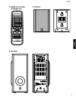
 REMOTE CONTROL

TRANSMITTER


 NX-S77E

 NX-SW77

Содержание AV-S77

Страница 1: ...uired should be performed by an authorized YAMAHA Retailer or the appointed service representative IMPORTANT The presentation or sale of this manual to any individual or firm does not constitute authorization certification or recognition of any applicable technical capabilities or establish a principle agent relationship of any form The data provided is believed to be accurate and applicable to th...

Страница 2: ...er and your skin When soldering do not inhale solder fumes or expose eyes to solder flux vapor If you come in contact with solder or components located inside the enclosure of this product wash your hands before handling food TO SERVICE PERSONNEL 1 Critical Components Information Components having special characteristics are marked s and must be replaced with parts having specifications equal to t...

Страница 3: ...AV S77 AV S77 2 REMOTE CONTROL TRANSMITTER NX S77E NX SW77 ...

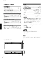
Страница 4: ...mption about 1W Max Dimensions W x H x D AV S77C 600 x 110 x 220 mm 23 5 8 x 4 5 16 x 8 11 16 NX SW77 176 x 405 x 433 mm 6 15 16 x 16 x 17 1 16 NX S77E 100 x 140 x 112 mm 3 15 16 x 5 1 2 x 4 3 8 Weight AV S77C 5 0kg 11 lbs NX SW77 11 0kg 24 lbs 4 oz NX S77E 0 8kg 1 lbs 12 oz Accessories Remote Controller Batteries R6P x 2 Audio Connection Cord 2 pin 3 m x 1 System Connector Cable 8 pin 3m x 1 Syst...

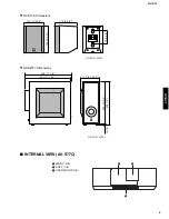
Страница 5: ...imensions NX SW77 Dimensions 100 3 15 16 140 5 1 2 112 4 3 8 Unit mm inch 70 2 3 4 Unit mm inch 435 17 1 8 433 17 1 16 176 6 15 16 400 15 3 4 405 16 5 3 16 INTERNAL VIEW AV S77C 1 MAIN P C B 2 DSP P C B 3 OPERATION P C B 1 2 3 ...

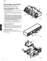
Страница 6: ...is fixed securely at 8 dowels When removing it use care not to cause a scratch or any damage to the main unit When reinstalling it apply quick drying type bond to the dowels of the Grille Assembly and fit it in place securely If it is only pushed in it will come off easily c Remove 8 screws 1 The OPERTION P C B can then be removed from the Grille Assembly Fig 1 2 Removal of Amplifier Unit a Remove...

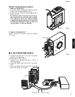
Страница 7: ... apply quick drying type bond to the dowels of the Grille Assembly and fit it in place securely If it is only pushed in it will come off easily 2 Removal of Amplifier Unit Remove 12 screws 5 and then remove the Amplifier Unit Fig 5 P C B OPERATION CHECK a Remove the Amplifier Unit referring to Disassembly procedures described above b Remove each P C B as required c Connect all the connectors betwe...

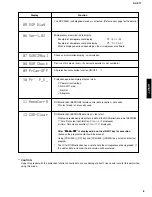
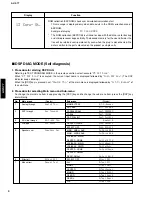
Страница 8: ...execution The normal mode will be restored 4 Details of the Test Program function Display 01 DEST B G1 Function Destination display test program end Destination display J Ja J Japanese B G1 B G models 03 FL CLEAR FL display segments all light up BACKUP RAM CLEAR 1st time FL display segments all light up and standby LED lights up 2nd time RAM CLEAR is executed RAM CLEAR OK on display State before s...

Страница 9: ...test mode is not usually used 12 COR Clear ROM collection EEPROM data clear clear start Display is provided only when there is data in the ROM collection area of EEPROM 1st time Data clear confirmation Clear ON displayed 2nd time Data clear execution Clear OK displayed After Clear ON Clear ON Clear ON Clear ON Clear ON is displayed do not use INPUT key for execution because the program contents wi...

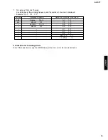
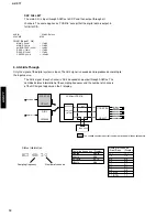
Страница 10: ...ed next Analog Thr of the main menu is displayed followed by A T M Bypass of the sub menu 2 Procedure for selecting Main menu and Sub menu To change the main menu item keep pressing the DSP key and to change the sub menu item press the DSP key intermittently No Main menu Display 1 Analog through Analog Thr 2 DSP through Dsp Through 3 AC 3 dts through AC 3 dts Thr 4 Pro logic Pro Logic 5 Speakers s...

Страница 11: ...ller 1 FL display of AC 3 dts Through A combination of the sampling frequency and the number of channels is displayed Example AC 3 32k 2 0 AC3 dts Sampling frequency Number of channels Front Rear AC3 Analog Analo 1 1 1 1 dts 32kHz 32k 1 0 1 0 44 1kHz 44 1k 2 0 2 0 48kHz 48k 3 0 3 0 2 1 2 1 3 1 3 1 2 2 2 2 3 2 5 1ch 3 2 7 1 DTS 7 1 ...

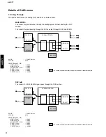
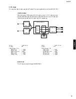
Страница 12: ...R signals pass through the DSP section MAIN BYPSS The main L R signal is output through the analog bypass without passing the DSP section The main L R signal passing through the DSP is output through C SW and RL RR The shaded square means that the element included in it does not operate AUX IN 20dBV Both ch VOLUME MAX CN301 Page 31 G3 MAIN L 1kHz 20dBV MAIN R 1kHz 20dBV SUBWOOFER 30Hz 34dBV REAR L...

Страница 13: ...L R signal is sent through AC3Dav into DSP After passing through SRAM the main L R signal is output through L R and C SW and RL RR signals through L R 2 YSS918 The main L R signal is sent through AC3Dav into DSP The main L R signal is output through L R and C SW and RL RR signals through L R 2 AUX IN 20dBV Both ch VOLUME MAX CN301 Page 31 G3 MAIN L 1kHz 20dBV MAIN R 1kHz 20dBV SUBWOOFER 30Hz 34dBV...

Страница 14: ... to the input source The AC 3 signal in each channel is AC 3 decoded and output through AC3Dav The combined status information of the sampling frequency and the number of channels of the AC3 signal appears on the Fl display Status information AC3 48k 3 2 Sampling frequency Number of channels Sampling frequency Display Analog Analo 32kHz 32k 44 1kHz 44 1k 48kHz 48k Number of channels Front Rear Dis...

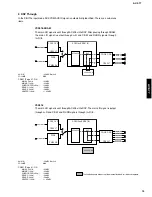
Страница 15: ... mode is used L R C S signals are pro logic decoded and output When the AC 3 mode other than 2 0 is used the pro logic function does not work and the signals are AC 3 reproduced EFFECT OFF The L R signal is output through MAIN BYPASS AUX IN 20dBV Both ch VOLUME MAX CN301 Page 31 G3 MAIN L 1kHz 45dBV MAIN R 1kHz 45dBV SUBWOOFER 30Hz 28dBV REAR L 1kHz 45dBV REAR R 1kHz 45dBV CENTER 1kHz 17dBV AUX IN...

Страница 16: ...E The center contents are distributed to the MAIN L R channels after 3dB SWFR SUBWOOFER Output The signal before MASTER VOLUME is indicated In Sub menu 1 the lower range content of the MAIN L R is output at SWFR as well In Sub menu 7 the lower range content of LFE CENTER and REAR is output at SWFR as well Sub menu Main application MAIN SMALL 0dB Confirmation of high low pass filter characteristics...

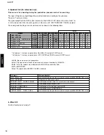
Страница 17: ...l CENTER Noise is output through the CENTER channel MAIN R Noise is output through the MAIN R channel REAR R Noise is output through the REAR R channel REAR L Noise is output through the REAR L channel LFE Noise is output through the LFE sub woofer channel The sensitivity setting of the Auto Power OFF function is as follows Display Sensitivity 1 Input signal level 3mVr m s 2 Input signal level 5mV...

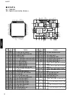
Страница 18: ...x 1 Synchronous output signal for DAC Fs x 1 Synchronous output signal for DSP Fs x 64Bit clock output Fs x 1Word clock output Fs x 128Bit clock output Fs x 256Bit clock output Clock synchronization control input Crystal oscillator connection or external clock input Crystal oscillator connection VCO oscillating clock connection PLL lock flag Logic section power GND PLL time constant switching outp...

Страница 19: ...MD4 RAMD3 RAMD2 RAMD1 RAMD0 VDD1 RAMA2 SCK SI SO CS CSB RAMA3 TEST IC RAMA4 VSS RAMA5 RAMA6 SDBCK0 SURENC KARAOKE MUTE CRC NONPCM VDD2 80 79 78 77 76 75 74 73 72 71 70 69 68 67 66 65 64 63 62 61 60 59 58 57 56 55 54 53 52 51 MICROPROCESSOR INTERFACE EXTERNAL RAM INTERFACE DA T A RAM CONTROL REGISTER CONTROL SIGNALS CONTROL SIGNALS L R LS RS C LFE STREAM0 7 SDIBCKSEL SDOACKSEL SDOBCKSEL ERAMUSE SDI...

Страница 20: ...SRAM address terminal 14 26 RAMA13 O External SRAM address terminal 13 27 RAMA12 O External SRAM address terminal 12 28 RAMA11 O External SRAM address terminal 11 29 RAMA10 O External SRAM address terminal 10 30 VSS Ground terminal for internal circuit 31 VDD1 5V power terminal for terminal section 32 OPORT0 O General purpose output terminal ISL0 DIGITAL INPUT SEL 33 OPORT1 O General purpose outpu...

Страница 21: ...ta terminal STREAM 5 output when external SRAM is not used 78 RAMD6 Itp O External SRAM data terminal STREAM 6 output when external SRAM is not used 79 RAMD7 Itp O External SRAM data terminal STREAM 7 output when external SRAM is not used 80 VSS Ground terminal for terminal section 81 VDD2 3 3V power terminal for internal circuit 82 SDWCK0 It Word clock input terminal for SDIA SDOA SDIB and SDOB s...

Страница 22: ...91 SBUSY2 P90 SRDY2 CNVSS P87 XCIN P86 XCOUT RESET XOUT VSS XIN VCC P85 INT5 P84 INT4 P83 INT3 P82 INT2 P81 INT1 P80 INT0 P77 TA4IN TA2OUT CTS1 RTS1 CLKS1 P76 TA3IN TA1OUT CLK1 P75 TA2IN TA0OUT RXD1 P74 TA1IN TA4OUT TXD1 P73 TA0IN TA3OUT P72 TB2IN P71 TB1IN P70 TB0IN IC200 M30217MA A208FP 16 bit µ COM No PORT Name IN OUT Function 1 P97 CMOS OUT BASS BOOST 0 ON 2 P96 CMOS OUT Center unit RL RR SW M...

Страница 23: ...IGIT 5 5G VEE external pull down required 48 P26 FLD38 OUT DIGIT 4 4G VEE external pull down required 49 P25 FLD37 OUT DIGIT 3 3G VEE external pull down required 50 P24 FLD36 OUT DIGIT 2 2G VEE external pull down required 51 P23 FLD35 OUT DIGIT 1 1G VEE external pull down required 52 P22 FLD34 OUT SEGMENT 1 P1 VEE external pull down required 53 P21 FLD33 OUT SEGMENT 2 P2 VEE external pull down req...

Страница 24: ... FLD4 OUT SEGMENT 31 P31 VEE internal pull down 85 P63 FLD3 OUT SEGMENT 32 P32 VEE internal pull down 86 P62 FLD2 OUT SEGMENT 32 P33 VEE internal pull down 87 P61 FLD1 OUT SEGMENT 34 P34 VEE internal pull down 88 P60 FLD0 OUT SEGMENT 35 P35 VEE internal pull down 89 VEE P0 P1 P5 P6 pull down resistance voltage input 29V 90 P107 AN7 A D IN SW protection IN 4 0 5 0V SW provided 0 2 0V SW protection ...

Страница 25: ...36 P5 35 P6 34 P7 33 P8 32 P9 31 P10 Pin No Connection Note 1 F1 F2 Filament 2 NP No pin 3 NX No extended pin 4 DL Datum Line 5 1G 13G Grid 12G 1G 1 1 1 2 1 3 1 4 1 5 1 6 1 7 2 1 2 2 2 3 2 4 2 5 2 6 2 7 3 1 3 2 3 3 3 4 3 5 3 6 3 7 4 1 4 2 4 3 4 4 4 5 4 6 4 7 5 1 5 2 5 3 5 4 5 5 5 6 5 7 13G 12G 1G P1 1 1 P2 2 1 P3 3 1 P4 4 1 P5 5 1 P6 1 2 P7 2 2 P8 3 2 P9 4 2 P10 5 2 P11 1 3 P12 2 3 P13 3 3 P14 4 3...

Страница 26: ...ock Data L R L R TV AUX VCR THROUGH FL RR RL LFE FR 4 27 6 8 4 2 8 2 6 4 7 3 UPC4570 IC308 DSP Control Signal 6 4 6 1 6 7 7 6 2 2 1 1 6 2 7 1 6 7 2 1 6 7 2 1 L R L R CB2 4 6 CB2 7 CB2 A G CN306 6 8 CN306 5 7 L R CT LF RL RR M SENSOR CN306 3 6 Signal Sensor IC10 UPC4570 IC11 UPC4570 IC11 UPC4570 IC309 2 21 20 22 26 24 23 25 IC12 UPC4570 IC12 UPC4570 C SW FL FR RL RR 6CH INPUT J model only UPC4570 6...

Страница 27: ... ISELB CONTROL 6ch Selector 6ch Volume ISEL A ISEL B CONTROL INPUT Selector 22 PD Power Down Detect Q209 D206 D207 B12V 12 RESET 91 M SENSOR Signal Detect For Auto Power MUSIC 89 29Vp VP 63 5V 100 14 Vs Vcc 16 65 97 AVs AVc SP RY1 36 38 RESET Circuit Q208 D205 ACG 12V 12V 5D 92 VPRT Voltage Moniter R459 R463 R464 R465 R460 R461 R217 35 90 SW PRT SW PRT 96 98 KEY INPUT 94 P ON IC200 M30218FCFP 24V ...

Страница 28: ...Q19 2 4 8 6 4 1 4 1 Power 12v 12v Relay Control 1 3 D14 R66 1 2 3 4 5 6 7 8 JK1 1 2 3 4 B 6 7 8 9 0 A C 5 MUTE Q3 Q2 JK2 B IC10 M5218AL IC10 M5218AL IC11 LM1875T IC12 LM1875T DC Signal Detect Q4 Q5 RY4 FRONT SPEAKER RELAY Q1 1 3 7 5 4 1 4 1 Q22 Q21 MUTE JK2 B CN9 Q6 F1 RY3 IC6 IC7 D13 D17 TR1 SW PRT JK2 1 Protection Circuit Q16 Q17 3 2 B2 B2 B1 B1 SW PRT JK2 1 D18 D1 D2 D3 D4 JK3 Headphone out Go ...

Страница 29: ...IN RL MAIN P C B Lead Type Device 1 2 AV S77C PRINTED CIRCUIT BOARD Foil side 31 30 Ref No Location D300 J5 D302 i4 D303 j4 D304 j4 D305 I4 D306 C3 D308 C5 D309 C3 D310 B3 D311 B3 D312 C3 Semiconductor Location Ref No Location D313 C2 D314 C5 D315 C5 D316 I5 D317 I5 IC304 G4 IC306 G5 IC308 I4 IC309 I4 IC310 E5 IC311 D3 Ref No Location IC312 F4 IC313 B5 IC314 B4 IC315 B5 IC316 F3 Q300 D3 Q302 D3 Q3...

Страница 30: ...D VSS RXDO CHVSS To OPERATION CE CTSD VSS RXDO CHVSS For CPU WRITER CE CLKD VCC TXDO RESET 33 32 AV S77C PRINTED CIRCUIT BOARD Foil side MAIN P C B Lead Type Device 2 2 Ref No Location D300 J2 D301 I3 D308 C3 D316 I2 D317 I2 IC301 F3 IC302 E3 IC303 I3 IC304 G3 IC306 G3 Semiconductor Location Ref No Location IC307 H3 IC313 B2 Q301 H3 Q303 H3 Q304 G3 Q305 G3 Q306 G3 Q310 H3 Q311 I3 ...

Страница 31: ...POWER TEST MODE for factory check INPUT DSP VOLUME VOLUME FLAC 10V 25V DGND CE CLK M SENSOR B BST SP RY2 NIGHT From MAIN FLAC VPRT 5V ISEL A POWER DATA HPSW ISEL B MUTE SP RY1 SW PRT STB CTSO VSS RXDO CNVSS From MAIN CE CLKO VCC TXDO RESET CEAC1 ICAC TXAC To DSP RXAC CEAC2 CLKAC ERRA CECOD CDO DG CLD SDT CCK ERRD SCK DG OPERATION P C B Lead Type Device OPERATION P C B Surface Mount Device AV S77C ...

Страница 32: ...C B Lead Type Device DSP P C B Surface Mount Device R L 12 RIN 5D RL C RR From MAIN E 12 LIN E LFE E E 36 AV S77C PRINTED CIRCUIT BOARD Component side 37 Ref No Location D1 C5 D2 D5 D3 I3 D4 I3 D5 E5 D6 E5 D7 E5 D8 E5 D9 E5 D10 E5 D11 E4 D12 E5 IC1 C5 IC2 C5 IC3 C5 IC4 C4 IC6 D5 IC7 C3 IC8 E3 IC9 E5 IC10 E4 IC11 D4 IC12 E4 IC14 D4 IC15 D5 Q1 C5 Q2 C5 Semiconductor Location ...

Страница 33: ...To AMP F CA4 To AMP E CA6 To AMP D CN5 From AMP D CN4 From POWER A CN11 From POWER A CN3 From POWER B CN10 To AMP D CN6 To AMP C CN7 To AMP D CN8 39 38 NX SW77 PRINTED CIRCUIT BOARD Foil side Ref No Location D6 E3 D7 E3 D8 D3 D9 E3 D10 E3 D11 E3 D16 H3 D19 E3 D20 E3 D21 G3 D22 D2 D23 D2 IC1 H4 IC2 D4 IC3 E4 IC4 D3 IC8 H2 IC9 H2 IC10 G4 IC11 G2 IC12 G2 IC13 D2 Semiconductor Location Ref No Location...

Страница 34: ...12V GND 12V To AMP C CA2 SP SW B2 VPRT 12V GND 12V AMPG B2 To AMP D CA1 To AMP E CA3 To AMP F CA4 From AC Power Cord Blue Brown To AMP E CA3 40 NX SW77 PRINTED CIRCUIT BOARD Component side 41 Ref No Location D1 I3 D2 I3 D3 I3 D4 I3 D5 E3 D12 E3 D13 D5 D14 C5 D15 H2 D17 F5 D18 E5 IC6 C4 IC7 C4 Semiconductor Location ...

Страница 35: ...78M12FA Voltage Regulator IC314 NJM78M05FA Voltage Regulator VOUT VIN GND IC315 NJM79M12FA Voltage Regulator COMMON OUTPUT INPUT Page 43 TO OPERATION A6 Page 43 TO OPERATION G7 INPUT SELECTOR MUTING DSP SELECTOR SIGNAL SENSOR DIGITAL VOLUME All voltage are measured with a 10MΩ V DC electric volt meter Components having special characteristics are marked s and must be replaced with parts having spe...

Страница 36: ...B MTZ6 2B PIN CONNECTION DIAGRAM OF TRANSISTORS DIODES AND ICS B E C M30218FCFP S 29390AFJA 1 4 8 1 30 31 50 51 80 81 100 Anode Cathode Point 3 Pin 13 of IC200 Point 4 emitter of Q209 and collector of Q208 POWER ON Connect the power cord POWER OFF Disconnect the power cord Q209 E Q208 C C Ch 1 Ch 2 5 1 5 1 0 2 5 1 0 Point C VCC of IC4 and OUT of IC4 Point B Pin 129 of IC3 POWER ON Connect the powe...

Страница 37: ... IC14 µPC29M33T E1 Voltage Regulator 3 OUTPUT 1 INPUT 2 GND Safety Drive Limiter Excessive Electric Current Protection Sudden Current Protection Starter Circuit Driver Standard Voltage Overheat Protection Amp IC15 TC74HC153AF Dual 4 to 1 Data Selectors 15 STROBE 2G 2 B SELECT 14 A SELECT 13 12 11 10 9 OUTPUT 2Y 1 STROBE 1G 3 4 5 6 7 OUTPUT 1Y 16 VCC 8 GND DATA INPUTS DATA INPUTS 2C3 2C2 2C1 B A 2C...

Страница 38: ...OM POWER G1 Page 46 FROM POWER F1 Page 45 FROM CA6 H7 Page 45 TO CN5 A4 Page 46 FROM POWER E1 Page 45 TO CN7 A5 Page 45 TO CN6 A2 SYSTEM CONNECTOR A SPEAKERS PHONES C SYSTEM CONNECTOR B s s s s s s s s MAIN L FRONT L REAR L LFE SW 0 0 11 8 11 6 11 4 24 8 25 0 0 0 0 0 0 11 4 0 0 0 24 8 25 0 0 0 0 24 8 4 5 0 25 0 0 0 0 24 8 25 0 0 0 0 0 4 5 0 0 7 0 1 0 0 4 5 0 0 4 5 0 0 7 0 1 0 0 24 7 0 1 24 7 0 1 0...

Страница 39: ...ark Blue Brown Brown Brown Blue Blue Page 45 TO AMP A7 Page 45 TO AMP A3 Page 45 TO AMP H2 Page 45 TO AMP H4 Page 45 TO AMP H4 IC7 NJM79M12FA Voltage Regulator COMMON OUTPUT INPUT 1 COM 2 IN 3 OUT INPUT OUTPUT COMMON IC6 NJM78M12FA Voltage Regulator 1 OUT 2 COM 3 IN 46 2SC1740S PIN CONNECTION DIAGRAM OF TRANSISTORS DIODES AND ICS 1SR139 1SS133 MTZJ5 6B RBV 602 NJM79M12FA NJM78M12FA E C B Anode Cat...

Страница 40: ...B COMB FILTER MODULE FLTR LC RF LC FILTER EMI GND MTL GROUND PLATE GND TERM GROUND TERMINAL HOLDER FUS FUSE HOLDER IC PRTCT IC PROTECTOR JUMPER CN JUMPER CONNECTOR JUMPER TST JUMPER TEST POINT L DTCT LIGHT DETECTING MODULE L EMIT LIGHT EMITTING MODULE LED DSPLY LED DISPLAY LED INFRD LED INFRARED MODUL RF MODULATOR RF PHOT CPL PHOTO COUPLER PHOT INTR PHOTO INTERRUPTER PHOT RFLCT PHOTO REFLECTOR PIN...

Страница 41: ...C EL 100uF 6 3V 066296 C63 AAX10400 C EL 0 47uF 50V 066462 C64 AAX11210 C POL 1500pF 50V 065028 C65 AAX11210 C POL 1500pF 50V 065028 C66 AAX10160 C EL 10uF 25V 066286 C67 AAX11240 C POL 3300pF 50V 065087 C68 AAX11240 C POL 3300pF 50V 065087 C69 AAX10160 C EL 10uF 25V 066286 C70 AAX10160 C EL 10uF 25V 066286 C71 AAX11190 C POL 1200pF 50V 065014 C72 AAX11230 C POL 0 27uF 50V 065082 C73 AAX10160 C EL...

Страница 42: ...V 065904 C363 AAX09970 C CE 0 01uF 50V 049191 Schm PART Description Remarks Ref NO New Parts AV S77C P C B AMP P C B DSP FL Schm PART Description Remarks Ref NO New Parts C364 AAX09970 C CE 0 01uF 50V 049191 C365 AAX09970 C CE 0 01uF 50V 049191 C369 FG212100 C CE 100pF 50V 065904 C370 UR857330 C EL 33uF 35V 066393 C371 AAX10160 C EL 10uF 25V 066286 C372 AAX10160 C EL 10uF 25V 066286 C373 AAX10160 ...

Страница 43: ...247A00 IC uPC4570HA 070111 s IC313 AAX11990 IC NJM78M12FA 070371 s IC314 XJ604A00 IC NJM78M05FA 070384 s IC315 AAX12000 IC NJM79M12FA 070447 IC316 XB247A00 IC uPC4570HA 070111 JK300 AAX28530 JACK RCA HSP 248V12 01 055460 JK310 AAX28180 JACK DIN 13P TCS5094 10 41 056981 JK312 AAX28170 JACK DIN 8P TC5073 28 4 056980 L1 GE300610 FER CORE FERITE CORE BL02RN 073729 L2 GE901970 COIL CHK LAV35VB 680K 055...

Страница 44: ...8KΩ 1 10W 067514 RD356200 R CAR CHP 2KΩ 1 10W RD356220 R CAR CHP 2 2KΩ 1 10W 067519 RD356270 R CAR CHP 2 7KΩ 1 10W 067526 RD356330 R CAR CHP 3 3KΩ 1 10W 067531 RD356360 R CAR CHP 3 6KΩ 1 10W RD356390 R CAR CHP 3 9KΩ 1 10W 067539 RD356470 R CAR CHP 4 7KΩ 1 10W 067545 RD356510 R CAR CHP 5 1KΩ 1 10W 085050 RD356560 R CAR CHP 5 6KΩ 1 10W 067553 RD356620 R CAR CHP 6 2KΩ 1 10W RD356820 R CAR CHP 8 2KΩ 1...

Страница 45: ...100 C EL 10uF 50V 066291 C65 AAX12270 C EL 330uF 16V 066402 C66 AAX12270 C EL 330uF 16V 066402 C67 AAX12250 C EL 22uF 50V 066352 C68 AAX12250 C EL 22uF 50V 066352 C69 AAX10370 C EL 4700uF 35V 066741 C70 AAX10370 C EL 4700uF 35V 066741 C71 AAX11280 C POL 0 047uF 50V 065118 C72 AAX11280 C POL 0 047uF 50V 065118 s C74 VS741700 C POL 0 01uF 275V 065262 C75 AAX12170 C CE 100pF 50V 051723 C76 AAX12170 C...

Страница 46: ...E 1 5uH 074417 L2 AAX12190 COIL CHOKE 1 5uH 074417 L3 AAX12190 COIL CHOKE 1 5uH 074417 L4 AAX12190 COIL CHOKE 1 5uH 074417 Q1 iC174020 TR 2SC1740S QRS 055717 Q2 iC287820 TR 2SC2878 A B 068813 Q3 iC287820 TR 2SC2878 A B 068813 Q4 iC287820 TR 2SC2878 A B 068813 Q5 iC174020 TR 2SC1740S QRS 055717 Q6 iC174020 TR 2SC1740S QRS 055717 Q7 iC287820 TR 2SC2878 A B 068813 Q8 iC287820 TR 2SC2878 A B 068813 Q9...

Страница 47: ...R Schm PART Description Remarks Ref NO New Parts s T1 AAX28510 TRANS SUB A1A1E0 1 337195 TM1 XX707320 PIN IPS 5007 064821 TM2 XX707320 PIN IPS 5007 064821 TM3 XX698880 LUG MET37 00O1 075878 TR1 iC174020 TR 2SC1740S QRS 055717 AAX10900 HEAT SINK DPS35 40 055524 BB070700 GND MTL 075884 ...

Страница 48: ... L 054710 6 AAX11340 FOOT 055583 7 AAX11370 PAD 054711 8 AAX10980 WASHER FILM 055592 9 EK336030 BW HEAD TAPPING SCREW 4x12 MFC2BL 10 AAX10860 BIND HEAD TAPPING SCREW 3x16 MFZN2BL 021373 11 AAX10870 BIND HEAD TAPPING SCREW 4x12 MFZN2BL 021379 12 EP600190 BIND HEAD B TITE SCREW 3x8 MFZN2BL 075638 13 AAX11360 WING BOLTS M4x0 7 057360 14 VB096700 BIND HEAD B TITE SCREW 2 6x8 MFZN2BL 15 AAX28650 REAR P...

Страница 49: ...8246 2 7 6 AAX12380 PAN HEAD B TITE SCREW 3x20 MFZN2BL 055430 2 7 7 V2128100 PW HEAD S TITE SCREW 3x12 8 MFZN2Y 2 7 8 AAX10110 INSULATOR MICA TO 220 044391 2 7 9 XV466A00 IC LM1875T 055041 2 7 10 AAX11050 CUSHION BUSH B 24 044543 2 8 AAX12160 BRACKET CLIP L80 A 078004 2 9 EP600190 BIND HEAD B TITE SCREW 3x8 MFZN2BL 075638 2 10 AAX10840 BIND HEAD B TITE SCREW 3x10 MFZN2BL 075640 2 11 EG340190 BIND ...

Страница 50: ...t No 1 0 Ω HJ35 3100 HF85 3100 1 8 Ω HJ35 3180 2 2 Ω HJ35 3220 HF85 3220 3 3 Ω HJ35 3330 HF85 3330 4 7 Ω HJ35 3470 HF85 3470 5 6 Ω HJ35 3560 HF85 3560 10 Ω HF45 4100 HF45 4100 15 Ω HJ35 4150 HF85 4150 22 Ω HF45 4220 HF45 4220 27 Ω HJ35 4270 HF85 4270 33 Ω HF45 4330 HF45 4330 39 Ω HJ35 4470 HF85 4390 47 Ω HF45 4470 HF45 4470 56 Ω HF45 4560 HF45 4560 68 Ω HF45 4680 HF45 4680 75 Ω HF45 4750 HF45 4750...

Страница 51: ...9 40 41 Preset TV Preset Preset Preset Preset Preset Preset Preset Preset Preset Preset Preset Preset Preset Preset Preset CODE SET DVD VCR MENU MENU MENU ENTER MENU MENU TITLE MENU STOP PAUSE PLAY SKIP SKIP SEARCH SEARCH Change VCR mode Change TV mode 78 0F 78 11 78 12 78 13 78 9D 78 48 78 5F 78 4E 78 9F 78 9E 78 50 78 9C 78 8A 78 5E 78 51 78 1E 78 8B 78 40 78 52 78 1F TV mode POWER TV INPUT TV V...

Отзывы: