background image


4


Chapter 2—Touring the AD824


AD824—Owner’s Manual


D


COM PC/RS422 port


This 9-pin D-sub connector is for connecting the AD824 to a device for remote control, 
such as a Yamaha DME32 or personal computer. It’s also used to connect to the previ-
ous AD824 in a multiple-unit system.


E


WORD CLOCK OUT connector


This BNC connector transmits the wordclock signal.


F


WORD CLOCK 75


 ON/OFF switch


This switch is used to terminate the wordclock signal received at the WORD CLOCK 
IN. See “Wordclocks” on page 14 for more information.


G


WORD CLOCK IN connector


This BNC connector is used to connect an external wordclock source. See “Wordclocks” 
on page 14 for more information.


H


INPUT (BAL) connectors


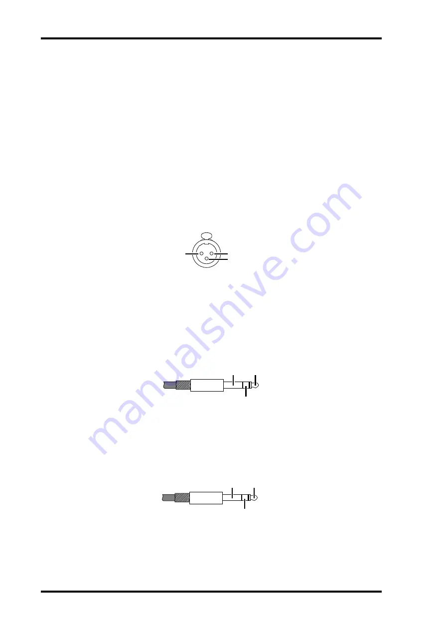
These female XLR-3-31-type connectors are the analog inputs. They’re electronically 
balanced and are wired as follows: pin-1 ground, pin-2 hot (+), and pin-3 cold (–).


I


SLOT


This slot is for use with optional mini YGDAI cards, which offer various digital output 
options. See “Digital I/O Cards” on page 7 for more information.


J


INSERT OUT (BAL) connectors


These balanced 1/4" TRS phone jacks are the insert outputs, or send connectors. The 
insert point on each channel is located between the head amplifier and A/D converter. 
They’re electronically balanced and are wired as follows: tip=hot, ring=cold, and 
sleeve=ground.


K


INSERT IN (BAL) connectors


These balanced 1/4" TRS phone jacks are the insert inputs, or return connectors. The 
insert point on each channel is located between the head amplifier and A/D converter. 
The signal level indicators are located after the INSERT IN connector. They’re electron-
ically balanced and are wired as follows: tip=hot, ring=cold, and sleeve=ground.

ground

hot

cold

ground

hot

cold

ground

hot

cold

Содержание AD824

Страница 1: ...er s Manual E ON OFF POWER AD CONVERTER 1 2 3 4 5 6 7 8 PEAK SIGNAL NOMINAL PEAK SIGNAL 48V SEL NOMINAL 48V WORD CLOCK INTERNAL 44 1kHz BNC SLOT 48kHz SEL dB GAIN OFF ON 48V MASTER Keep This Manual For Future Reference ...

Страница 2: ...0 The above statements apply ONLY to those products distributed by Yamaha Corporation of America or its subsidiaries WARNING THIS APPARATUS MUST BE EARTHED IMPORTANT THE WIRES IN THIS MAINS LEAD ARE COLOURED IN ACCORDANCE WITH THE FOLLOWING CODE GREEN AND YELLOW EARTH BLUE NEUTRAL BROWN LIVE As the colours of the wires in the mains lead of this apparatus may not correspond with the coloured markin...

Страница 3: ... fire and electrical shock hazard Do not plug several devices into the same AC outlet This may overload the AC outlet andcouldbeafireorelectricalshockhazard Itmayalsoaffecttheperformanceof some equipment If you notice any abnormality such as smoke odor or noise or if a foreign object or liquid gets inside the AD824 turn it off immediately Remove the power cord from the AC outlet and consult your d...

Страница 4: ...d to acclimatize for about one hour before use When the wordclock source is changed on the wordclock master device e g this AD824 a DME32 or 02R noise may occur from the outputs of the wordclock slave devices especially a AD824 with an MY8 AT I O card installed so turn down your power amps beforehand otherwise any connected speakers may be damaged If the error code E1 or E3 appears on the GAIN dis...

Страница 5: ...demarks of Teac Corporation Yamaha is a trademark of Yamaha Corporation All other trade marks are the property of their respective holders and are hereby acknowledged Copyright No part of the AD824 software or this Owner s Manual may be reproduced or distrib uted in any form or by any means without the prior written authorization of Yamaha Corporation 2000 Yamaha Corporation All rights reserved ...

Страница 6: ...ain 6 Controlling the AD824 Remotely 6 4 Digital I O Cards 7 About Digital I O Cards 7 Card Specifications 7 Installing I O Cards 8 5 Hookup Examples 9 Basic AES EBU Connection 9 Basic ADAT Connection 9 AES EBU Connection with Splitter Cable 10 Dual ADAT Connection 10 Insert Connection 11 Personal Computer Connection 11 Yamaha DME32 Connection 12 Multiple AD824 Connection 13 6 Wordclocks 14 About ...

Страница 7: ...ocol Installation The AD824 can be used freestanding on a stable surface somewhere that complies with the important information at the beginning of this manual or mounted in a rack When mounting the AD824 in a rack leave adequate ventilation space around the AD824 at least 10 cm of free space behind If the AD824 is mounted in a portable rack case keep the rear of the case open when using the AD824...

Страница 8: ...itch is used to turn on the power to the AD824 See Turning On the Power on page 1 for more information F WORD CLOCK indicators These indicators show the selected wordclock source When the AD824 cannot lock to the selected source the corresponding indicator flashes G WORD CLOCK Source button This button is used to select the wordclock source 44 1 kHz internal 48 kHz internal BNC or SLOT H Channel S...

Страница 9: ... AD824 to the next AD824 in a mul tiple unit system C COM PC RS422 switch This switch should be set to RS422 when the COM PC RS422 port is connected to a DME32 or the previous AD824 in a multiple unit system or PC when it s connected to a PC Security Cover For certain applications you may wish to fit a protective cover over the AD824 s GAIN controls and switches Although Yamaha do not make such a ...

Страница 10: ...hey re electronically balanced and are wired as follows pin 1 ground pin 2 hot and pin 3 cold I SLOT This slot is for use with optional mini YGDAI cards which offer various digital output options See Digital I O Cards on page 7 for more information J INSERT OUT BAL connectors These balanced 1 4 TRS phone jacks are the insert outputs or send connectors The insert point on each channel is located be...

Страница 11: ...er for Each Channel The 48V phantom power can be turned on and off for each channel individually 1 Use the SEL buttons to select a channel The selected channel s SEL indicator lights up 2 Press the 48V on off button The channel s 48V indicator flashes quickly 3 While the indicator is flashing press the 48V button again to turn the chan nel s 48V phantom power on or off The channel s 48V indicator ...

Страница 12: ...ng an exclusive control protocol the AD824 can be remotely controlled from a Yamaha DME32 personal computer or other device connected to the COM PC RS422 port In addition several AD824s can be remotely controlled by connecting them together in a chain like fashion by using both the COM PC RS422 port and the COM RS422 port When a control signal is detected the GAIN display indicates the AD824 s ID ...

Страница 13: ... AES EBU The MY8 AE card provides AES EBU format digital I O via a 25 pin D sub connector and supports 16 20 and 24 bit wordlengths MY8 TD Tascam TDIF 1 The MY8 TD card provides Tascam TDIF 1 format digital I O via a 25 pin D sub con nector and supports 16 20 and 24 bit wordlengths A BNC connector is provided for wordclock output MY8 TD cards feature a device selector switch EXT 88 INT 38 that sho...

Страница 14: ...d fixing screws in a safe place for future use 3 Insert the card between the guide rails and slide it all the way into the slot as shown below You may have to push firmly to plug the card into the AD824 connector 4 Secure the card using the attached thumbscrews Do not leave the thumb screws loose as the card will not be grounded correctly COM 8 8 8 SLOT OUT PC RS422 75Ω IN ON OFF W ORD CLOCK COM 8...

Страница 15: ...xample shows how the AD824 can be connected to a digital audio device with an ADAT interface by using a MY8 AT I O card and stan dard ADAT connecting cable The AD824 is the wordclock master In order to use the digital audio device as the wordclock master its word clock signal would need to be fed to the AD824 using the SLOT ADAT IN or BNC WORD CLOCK IN Digital Audio Device DME32 02R D24 etc AES EB...

Страница 16: ... the AD824 receiving its wordclock via a BNC connection the DA824 via its slot input Digital Audio Device DME32 02R D24 etc Analog input x8 Analog output x8 Custom AES EBU splitter cable SLOT MY8 AE SLOT MY8 AE AES EBU I O BNC cable WC OUT WC IN AD824 DA824 ON OFF POWER DA CONVERTER LOCK PEAK SIGNAL NOMINAL PEAK SIGNAL NOMINAL 1 2 3 4 5 6 7 8 ON OFF POWER AD CONVERTER 1 2 3 4 5 6 7 8 PEAK SIGNAL N...

Страница 17: ... for remote control The computer is connected to the AD824 s COM PC RS422 port and the COM PC RS422 switch is set to PC Digital Audio Device DME32 02R D24 etc Outboard equipment AES EBU cable SLOT MY8 AE INSERT IN OUT Input Output AES EBU I O Analog intput x8 AD824 ON OFF POWER AD CONVERTER 1 2 3 4 5 6 7 8 PEAK SIGNAL NOMINAL PEAK SIGNAL 48V SEL NOMINAL 48V WORD CLOCK INTERNAL 44 1kHz BNC SLOT 48k...

Страница 18: ... wordclock via a BNC connection the DA824 via its slot input Analog input x8 Custom AES EBU splitter cable SLOT MY8 AE SLOT MY8 AE AES EBU I O Analog output x8 DME32 SCENE NO CONFIGURATION 48kHz LOCK EMERGENCY 44 1kHz SCENE COMPONENT PARAMETER UTILITY VALUE CARD USER DEFINE PROTECT INC DEC DIGITAL MIXING ENGINE POWER ON OFF 7 8 9 4 5 6 1 2 0 STORE RECALL 3 SCENE RECALL DATA XDigitalXMixingXEngine ...

Страница 19: ...able COM PC RS422 COM SLOT 1 SLOT 2 Analog input x8 9 pin cable COM PC RS422 SLOT SLOT COM RS422 COM RS422 Analog input x8 AD824 1 AD824 2 ON OFF POWER AD CONVERTER 1 2 3 4 5 6 7 8 PEAK SIGNAL NOMINAL PEAK SIGNAL 48V SEL NOMINAL 48V WORD CLOCK INTERNAL 44 1kHz BNC SLOT 48kHz SEL dB GAIN OFF ON 48V MASTER ON OFF POWER AD CONVERTER 1 2 3 4 5 6 7 8 PEAK SIGNAL NOMINAL PEAK SIGNAL 48V SEL NOMINAL 48V ...

Страница 20: ...wn the same cable This works okay with AES EBU and Tascam TDIF 1 digital con nections becauseasinglecableis all that s required to transmit and receive digital audio With the ADAT format however sep arate optical cables are used to transmit and receive so in order to transmit digital audio and derive a wordclock signal both the ADAT IN and OUT on the AD824mustbeconnectedtothe digital audio device ...

Страница 21: ...on is applied at the last device only Daisy Chain Distribution In this example the wordclock signal is distributed in a daisy chain fashion with each device feeding the wordclock signal on to the next Termination is applied at the last device only This method of distribution is not recommended for larger systems Device A Termination ON Device B Device C Device D Termination ON Termination ON Termi...

Страница 22: ...ic range1 110 dB typical GAIN 10 dB Gain error 1 dB 1 kHz GAIN 62 dB to 10 dB THD2 0 1 4 dB output 20 Hz 20 kHz GAIN 62 dB 0 05 full scale output 1 kHz GAIN 62 dB 0 05 4 dB output 20 Hz 20 kHz GAIN 10 dB 0 01 full scale output 1 kHz GAIN 10 dB Hum noise level1 92 dB typical Rs 150 Ω GAIN 10 dB 62 dB Rs 150 Ω GAIN 62 dB Equivalent input noise1 128 dB Rs 150 Ω GAIN 62 dB Crosstalk 70 dB between adja...

Страница 23: ...io n GAIN Actual Load Impedance For Use with Nominal Input Level Connector Nominal Max before clip INPUT 1 81 1 24 bit linear 128 times oversampling A D converters 62 dB 3k Ω lines 50 600 Ω mics 600 Ω lines 62 dB 615 µV 48 dB 3 08 mV XLR 3 31 type balanced 2 2 XLR type connectors are electronically balanced pin 1 ground pin 2 hot pin 3 cold 10 dB 10 dB 2 45 V 24 dB 12 28 V INSERT IN 1 8 10k Ω 600 ...

Страница 24: ...t E1 E2 E3 and E4 Connection Format Level Impedance Connector COM PC RS422 RS232C RS422 9 pin D sub male COM RS422 RS422 9 pin D sub WORD CLOCK IN TTL 75Ω ON OFF BNC WORD CLOCK OUT TTL 75Ω BNC SLOT mini YGDAI 67 5 67 5 345 35 35 410 430 13 88 H 97 5 30 30 48 33 274 10 8 45 17 355 D 377 6 W 480 Unit mm YAMAHA CORPORATION Pro Audio Digital Musical Instrument Division P O Box 3 Hamamatsu 430 8651 Jap...

Отзывы: