ELEC
Electrical systems
–
+
31
60L3D1X
Fuel control system
8
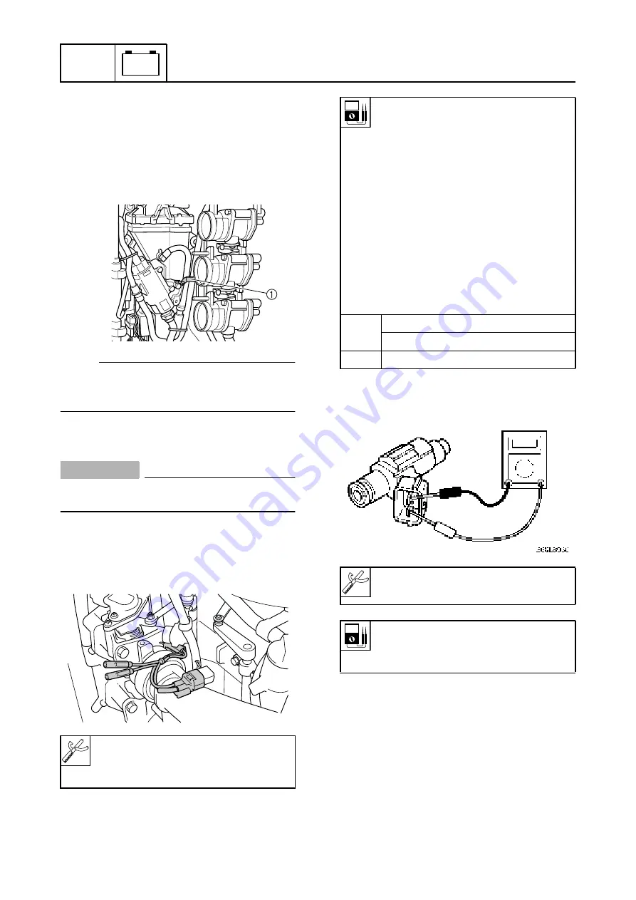
Checking the fuel injector
1.
Remove the intake silencer and discon-
nect the fuel injector coupler.
2.
Connect the test harness (2 pins) to the
fuel injector.
NOTE:
Before connecting the test harness to the fuel
injector of cylinder #4, remove the vapor sep-
arator bracket
1
.
3.
Install the intake silencer.
CAUTION:
Do not start the engine when the intake
silencer is not installed.
4.
Measure the fuel injector output peak
voltage. If out of specification, measure
the fuel injector resistance.
5.
Measure the resistance of the fuel injec-
tors. Replace if out of specification.
Digital circuit tester: 90890-03174
Peak voltage adaptor: 90890-03172
Test harness (2 pins): 90890-06861
S60L8010
S60L8020
Fuel injector output peak voltage
(use as reference):
#1 Red/yellow (R/Y) –
Orange/red (O/R)
#2 Red/yellow (R/Y) –
Orange/black (O/B)
#3 Red/yellow (R/Y) –
Orange/yellow (O/Y)
#4 Red/yellow (R/Y) –
Orange/red (O/R)
#5 Red/yellow (R/Y) –
Orange/black (O/B)
#6 Red/yellow (R/Y) –
Orange/yellow (O/Y)
r/min
Loaded
1,500–3,000
DC V
38–40
Digital circuit tester: 90890-03174
Fuel injector resistance
(use as reference):
14.0–15.0
Ω
at 20 °C (68 °F)
https://www.boat-manuals.com/
Содержание 60L
Страница 1: ...SERVICE MANUAL 292087 60L 28197 3D 1X SUPPLEMENTARY F200A FL200A https www boat manuals com ...
Страница 51: ...https www boat manuals com ...
Страница 53: ...https www boat manuals com ...
Страница 54: ...YAMAHA MOTOR CO LTD Printed in the Netherlands Aug 2001 1 3 1 CR F200AET FL200AET E https www boat manuals com ...


