19
Tyros2
NITOR SPEAKER
RS-MS02
ER’S MANUAL
ENUNGSANLEITUNG
E D’EMPLOI
14-4
Black Key
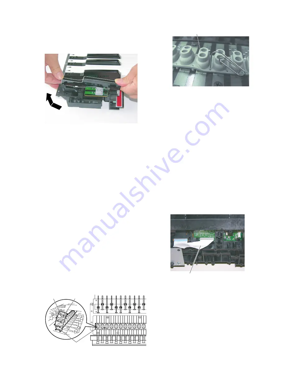
14-4-1 Remove both adjacent white keys first. (Fig.7A)
14-4-2 While pressing the black key backward keeping it in a
horizontal position, lift and remove it. (Fig.7B)
(Fig.7B)
15.
Assembling White (Black) Key
15-1
White Key
15-1-1 While pressing the white key backward keeping it in a
horizontal position, lower and insert it into the frame.
(Fig.7A)
*
At that time, do not lower the near side of the white key
too much and take care not to bend the key guide cap.
(Fig.7C)
*
Install the black key first, and then install both adjacent
white keys.
15-2
Black Key
15-2-1 Install the black key in the same manner as the white
key. (See procedure 15-1-1.)(Fig.7B)
15-2-2 Install the removed key stoppers L, H and 61. (Fig.7)
16.
Rubber Contact
16-1
Separate the unit into the upper case assembly and the
lower case assembly. (See procedure 1.)
16-2
Remove the necessary key stopper and the key referring
to the table in Fig.7. (Fig.7)
16-3
Pull and remove the rubber contact. (Fig.9)
*
As for the rubber contact, the direction of the installation
is specified. Take care not to install the rubber contact
reversly. (Fig.9)
*
When installing the rubber contact, confirm that a dust
does not adhere to the contact points first. Then, push the
rubber contact using the tip of clip and install it. (Fig.7D)
Contact(Long)
Rubber Contact
Contact(Short)
(Fig.9)
(Fig.7D)
17.
MK61L Circuit Board
(Time required: About 7 minutes)
17-1
Separate the unit into the upper case assembly and the
lower case assembly. (See procedure 1.)
17-2
Remove the key stoppers L and H. (See procedure 14-2.)
17-2
Remove the keys and the key springs from C1 to C4.
(See procedure 14.)
17-3
Remove the thirteen (13) screws marked [250A], and
remove the FFC cable for CN1 from the back side of the
keyboard assembly.
The MK61 circuit board can then be removed. (Fig.8,
Fig.7E)
*
When installing the MK61 circuit board, put the circuit
board under the positioning ribs first, and then tighten
the screws. (Fig.8)
*
As for the service parts, the rubber contact is not
included in the MK61L circuit board.
When replacing the MK61L circuit board, remove all the
rubber contacts from the circuit board to be replaced, and
install them to new circuit board.
FFC Cable
(Fig.7E)
18.
MKH-D and EMKS-FD Circuit Boards
(Time required: About 6 minutes)
18-1
Separate the unit into the upper case assembly and the
lower case assembly. (See procedure 1.)
18-2
Remove the key stoppers H and 61. (See procedure 14-2.)
18-3
Remove the keys and the key springs from C#4 to C6.
(See procedure 15.)
18-4
Remove the nine (9) screws marked [250B]. (Fig.8)
18-5
Remove the FFC cable (for CN4) from the back side of
the keyboard assembly. The MKH-D and EMKS-FD
circuit boards can then be removed. (Fig.8, Fig.7E)
Rubber Contact
Содержание 2
Страница 47: ...47 Tyros2 2NA WE84370 2 2 F F to DAC2A CN101 to LCL CN1 to AJK CN7 Pattern Side ...
Страница 57: ...57 Tyros2 Note See parts list for details of circuit board component parts P P Pattern Side 2NA WE81690 4 ...
Страница 61: ...61 Tyros2 Note See parts list for details of circuit board component parts R R Pattern Side 2NA WE81690 4 ...
Страница 64: ...64 Tyros2 Note See parts list for details of circuit board component parts PNR Circuit Board T T ...


