Metering
79
03D—Owner’s Manual
Metering
Level meters for the 24 input channels, stereo input channel, aux sends, bus outs, effects
returns, YGDAI outputs, and Solo bus are provided on the three Meter pages. The sig-
nal source points for input and output meters can be set on Pre/Post page. Meters can
be used to meter signal levels or the amount of gain reductions being applied by the
dynamics processors. Stereo out levels are metered using the dedicated L STEREO R
LED meters. A switchable peak hold function can be set globally for all meters.
Meter page level meters range from –48 dB to 0 dB, with CLIP. The CLIP indicators
light up when signals actually clip. So if a CLIP indicator lights up, back off the level a
little. Otherwise, signal distortion may occur.
1. Use the [FADER] button to select the Meter pages.
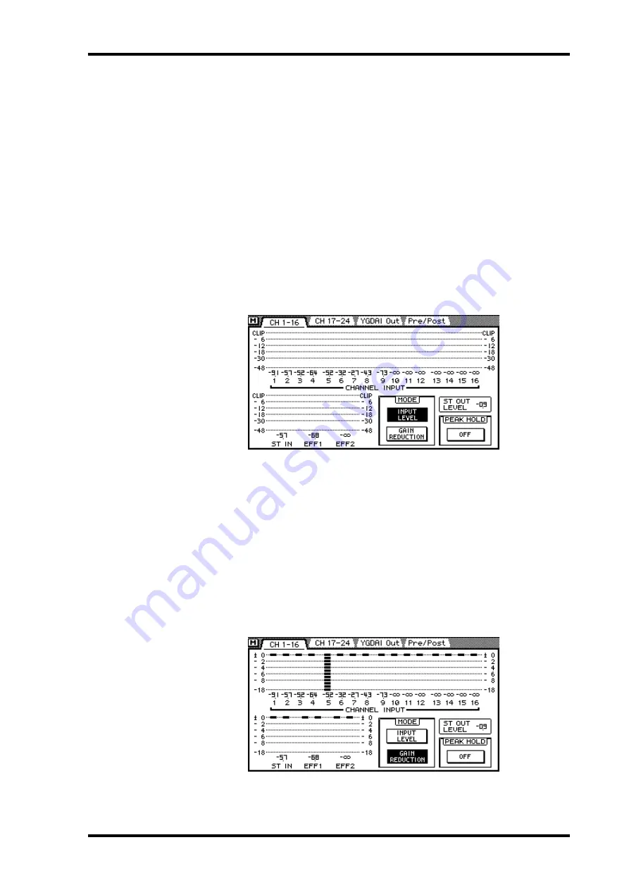
The CH 1–16 page, which is shown below, contains level meters for input channels 1 to
16, the stereo input channel, and effects returns 1 and 2. The decibel value below each
meter indicates the position of the corresponding channel fader. The position of the ste-
reo out fader appears in the ST OUT LEVEL box.
2. Use the cursor buttons to select a MODE switch, and then press the
[ENTER] button to activate that mode.
If you are using a mouse, simply click a MODE switch.
MODE
—Level meters can be used as input levels meters or gain reduction meters. In
INPUT LEVEL mode, meters function as typical level meters. In GAIN REDUCTION
mode, the meters show the amount of gain reduction being applied by the dynamics
processors. Gain reduction meters are also available on the Dyn. Edit page. See Dynam-
ics Processors on page 143 for more information.
The MODE switches also appear on the CH 17–24 meter page.
On the following display page, the meter mode is set to gain reduction and the noise
gate patched into channel 5 is shown as being closed.


