background image

10

Control Surface & Rear Panel

01V96i—Reference Manual

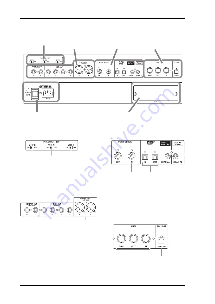
Rear Panel

P48V

1

CH1–4 ON/OFF switch

2

CH5–8 ON/OFF switch

3

CH9–12 ON/OFF switch

AD Output Section

1

MONITOR OUT connectors L/R

2

OMNI OUT connectors 1–4

3

STEREO OUT connectors L/R

Digital I/O Section

1

WORD CLOCK OUT connector

2

WORD CLOCK IN connector

3

ADAT IN/OUT connectors

4

2TR OUT DIGITAL COAXIAL

5

2TR IN DIGITAL COAXIAL

MIDI/USB Section

1

MIDI IN/THRU/OUT ports

2

TO HOST USB port

P48V (p. 10)

Power Section (p. 11)

AD Output Section 
(p. 10)

SLOT Section (p. 11)

MIDI/USB Section 
(p. 10)

Digital I/O Section 
(p. 10)

3

2

1

3

2

1

4

2

1

5

3

2

1

Содержание 01V96i

Страница 1: ... previous next view in your viewing history This is a convenient way to jump back to the previous page after you ve used a link to jump to a different page Using the Function Tree A function tree for the 01V96i is provided on page 4 and fol lowing You can use this to quickly find the explanatory page you want Note The latest version of Adobe Reader can be downloaded from the following URL http www...

Страница 2: ... Compressor Parameters 62 Internal Effects 64 About the Internal Effects 64 Using Effects Processors via Aux Sends 64 Inserting the Internal Effects into Channels 65 Editing Effects 66 About Add On Effects 67 About Plug Ins 67 Scene Memories 68 About Scene Memories 68 What is Stored in a Scene 68 About Scene Numbers 68 Storing and Recalling Scenes 69 Auto Scene Memory Update 70 Fading Scenes 71 Re...

Страница 3: ...k Connections and Settings Input and Output Patching Tutorial Input and Output Patching Setting the Input Levels Pairing Channels Setting the Routing EQ ing the Input Signals Using the EQ Library Compressing the Input Signals Using the Internal Effects Recording to DAW Software via the USB Port Adjusting the Monitor Levels from the DAW Using Scene Memories Changing the Channel Names Creating a Cus...

Страница 4: ...IT 56 SURR1 16 INPUT CH1 16 SURROUND 58 SURR17 32 INPUT CH17 32 SURROUND 58 SURR ST IN STEREO INPUT SURROUND 58 PAIR GROUP INPUT INPUT PAIR 27 OUTPUT OUTPUT PAIR 33 IN FADER INPUT FADER GROUP 59 IN MUTE INPUT MUTE GROUP 59 OUT FADER OUTPUT FADER GROUP 59 OUT MUTE OUTPUT MUTE GROUP 60 IN EQ INPUT EQUALIZER LINK 62 OUT EQ OUTPUT EQUALIZER LINK 62 IN COMP INPUT COMP LINK 63 OUT COMP OUTPUT COMP LINK ...

Страница 5: ... CH1 16 AUX VIEW 40 VIEW17 STI INPUT CH17 ST IN AUX VIEW 40 HOME METER CH1 32 CH1 32 METER 8 ST IN ST IN METER 8 MASTER MASTER METER 8 EFFECT EFFECT1 4 INPUT OUTPUT METER 8 STEREO STEREO METER 8 POSITION METER POSITION 8 BUTTON FUNCTION PAGE NAME LINK 1 16 8 17 32 8 MASTER 8 REMOTE USER DEFINED 94 ProTools 83 Nuendo 93 Cubase 93 General DAW 94 USER ASSIGNABLE LAYER 110 ...

Страница 6: ...4 INPUT BAL INSERT OUT IN UNBAL ST IN 1 ST IN 2 USER DEFINED KEYS 1 2 3 4 5 6 7 8 5 5 5 10 5 10 10 10 15 15 15 20 20 20 30 30 30 30 40 40 40 50 50 50 60 60 70 70 20 30 40 40 50 50 60 70 0 0 5 10 15 20 0 0 5 10 5 10 15 30 20 30 40 40 50 50 60 70 20 30 40 40 50 50 60 70 20 30 40 40 50 50 60 70 20 30 40 40 50 50 60 70 20 30 40 40 50 50 60 70 15 0 5 10 15 20 0 5 10 5 10 0 30 15 5 10 15 20 0 5 10 5 10 ...

Страница 7: ...IGNAL PEAK SIGNAL PEAK SIGNAL PEAK SIGNAL PEAK SIGNAL PEAK SIGNAL PEAK SIGNAL CH15 16 2TR IN 4 26 GAIN 4 26 GAIN 4 26 GAIN GAIN 4 26 GAIN 20dB 16 60 GAIN 20dB 16 60 GAIN 20dB 20dB 20dB 20dB 20dB 20dB 20dB 16 60 GAIN 16 60 GAIN 16 60 GAIN 16 60 GAIN 16 60 GAIN 16 60 GAIN 16 60 PAD A B A B A B A B A B A B A B A B A B 16 15 13 12 11 10 9 4 3 2 1 5 14 INSERT I O INSERT I O INSERT I O INSERT I O INSERT...

Страница 8: ...ROUP button 8 PATCH button 9 DYNAMICS button 0 EQ button A EFFECT button B VIEW button LAYER Section 1 1 16 17 32 buttons 2 MASTER button 3 REMOTE button ON SEL 5 10 15 20 30 40 50 60 70 0 STEREO 1 2 3 SOLO ON SOLO ON SEL SEL ST IN ST IN 1 ST IN 2 1 2 3 4 5 FADER MODE AUX 1 AUX 2 AUX 3 AUX 4 AUX 8 AUX 7 AUX 6 AUX 5 HOME METER 1 2 Tip The ST IN section is not affected by the layer settings DISPLAY ...

Страница 9: ...on trol 8 GAIN control SCENE MEMORY Section 1 STORE button 2 Scene Up Down buttons 3 RECALL button USER DEFINED KEYS Section 1 1 8 buttons Data Entry Section 1 Parameter wheel 2 ENTER button 3 DEC INC buttons 4 Left Right Up Down cur sor buttons SOLO Section 1 SOLO indicator 2 CLEAR button STEREO OVER 0 3 6 9 12 15 18 24 30 36 48 4 1 5 2 3 6 Tab Scroll arrow HIGH HIGH MID LOW MID LOW Q FREQUENCY G...

Страница 10: ... connectors 1 4 3 STEREO OUT connectors L R Digital I O Section 1 WORD CLOCK OUT connector 2 WORD CLOCK IN connector 3 ADAT IN OUT connectors 4 2TR OUT DIGITAL COAXIAL 5 2TR IN DIGITAL COAXIAL MIDI USB Section 1 MIDI IN THRU OUT ports 2 TO HOST USB port PHANTOM 48V p 10 Power Section p 11 AD Output Section p 10 SLOT Section p 11 MIDI USB Section p 10 Digital I O Section p 10 3 2 1 3 2 1 4 2 1 5 3 ...

Страница 11: ...Rear Panel 11 01V96i Reference Manual Control Surface Rear Panel SLOT Section 1 SLOT Power Section 1 POWER ON OFF switch 2 AC IN connector 1 2 1 ...

Страница 12: ...ternal devices such as effects processors into AD Input Channels Phantom Power Inputs 1 through 12 feature switch able 48V phantom powering for use with con denser typemicrophonesanddirectboxes Thephantom 48V switchesontherearpanelturnonoroffthe 48V phantom power feed to the corresponding inputs PAD switches Inputs 1 through 12 feature pad switches which attenuate input signals by 20 dB These swit...

Страница 13: ...IGITALisanRCAphonoconnector and accepts consumer format IEC 60958 digital audio You can patch digital signals input at this connector to any Input Channel page 43 2TR OUT DIGITAL connector This RCA phono connector outputs con sumer format IEC 60958 digital audio You can patch any Bus outs or Input channel Direct Outs to this output page 45 ADAT IN connector This TOSLINK connector accepts 8 channel...

Страница 14: ...he following buttons to select a slot or connector for which you want to view the channel status 1 2TR IN This button enables you to view the Channel Status of input signals connected to the 2TR Digital Inputs 2 SLOT These buttons enable you to view the Channel Status of each two adjacent odd and even in this order channel signals connected to the digital I O card installed in the slot 2 Move the ...

Страница 15: ...ettings are displayed at the bottom of the page 2 Move the cursor to the output or channel to which you want to apply dithering then rotate the Parameter wheel or press the INC DEC buttons to select the value that matches the resolution of the receiving device Parameter value Description General Temporarily used Laser Optical Laser optical device D D Conv Digital Digital converter and signal proce...

Страница 16: ...operatingat a higher sampling rate and an external digital device that supports 44 1 48 kHz DOUBLE SPEED In Double Speed mode digital audio data is received and transmitted at the current high sampling rate i e 88 2 kHz or 96 kHz Select this mode if the devices that support the higher sampling rates transmit or receive data SINGLE In Single mode digital audio data is received and trans mitted at a...

Страница 17: ...elay effect with feedback ON On Off This section enables you to turn the channel on or off The channel is muted with the Off setting LEVEL This section enables you to adjust the input level of the Input Channel signal PAN This section enables you to adjust the pan setting of the signals routed from the Input Channels to the Stereo Bus You can also apply the pan setting to a pair of Bus chan nels A...

Страница 18: ... 32 page This page enables you to set the Delay function for Input Channels 17 32 The parameters on these two pages and the procedure for setting them are the same 1 DELAY SCALE The following buttons determine the units of the delay value shown below the msec value meter Units are set to meters feet Units are set to feet sample Units are set to samples beat Units are set to beats frame Units are s...

Страница 19: ...cate the levels of the post gate signals and the amount of gain reduction 6 ON OFF The ON OFF button turns the currently selected Input Channel s gate on or off 7 PARAMETER These controls enable you to set the gate parameters See page 148 for more information on the parameters Tip This function is unavailable for the ST IN Channels The delay time range depends on the sampling rate at which the 01V...

Страница 20: ...or signals and the amount of gain reduction 6 ON OFF The ON OFF button turns the currently selected Input Channel s compressor on or off 7 PARAMETER section These controls enable you to set the compressor parame ters See page 149 for more information on the parame ters of each compressor type Attenuating Input Channels To set the attenuator for each Input Channel press the DIS PLAY ACCESS EQ butto...

Страница 21: ...ut Channel and its available pair partner 6 LOW L MID H MID HIGH sections These sections contain the Q Frequency F and Gain G parameters for the four bands These parameter val ues range as follows 3 Move the cursor to the desired parameter then rotate the Parameter wheel to change the value 6 5 1 2 3 4 Parameter LOW LOW MID HIGH MID HIGH Q HPF 10 0 to 0 10 41 steps L SHELF 10 0 to 0 10 41 steps LP...

Страница 22: ...elow that contains the desired channels appears ROUT1 16 page This page enables you to change the routing for Input Channels 1 16 ROUT17 ST1 page This page enables you to change the routing for Input Channels 17 32 and ST IN Channels 1 4 The parameters on these two pages and the procedure for setting them are the same 1 PAN buttons These buttons determine whether the channel s Pan set ting is appl...

Страница 23: ...IEW button repeatedly Move the cursor to a parameter you wish to change then rotate the Parameter wheel or press the INC DEC buttons or ENTER button to modify the setting The following parametersare available sections marked with an asterisk are unavailable for the ST IN Channels 1 GATE section This section enables you to turn the gate type dynamics processor on or off and set the parameters See p...

Страница 24: ... Surround pan parameters for the currently selected Input Channelaredisplayed onlywhen aSurround mode is selected See page 52 for more information on Sur round pan 3 BUS ROUTING FOLLOW PAN section BUS ROUTING ThissectionenablesyoutoselectadestinationBusforthe selected channel When the D button is turned on the channel signal is patched to the Direct Out selected in the parameter box below the butt...

Страница 25: ... for control by the ST IN section 2 Press the SEL button for the channel for which you want to adjust the level and or pan settings 3 Rotate the level control of the desired chan nel to set the level You can always view the current channel level at the top of the display 4 Rotate the SELECTED CHANNEL PAN con trol to adjust the pan setting The pan setting can be applied to either ST IN channel L or...

Страница 26: ... ATT page but the paired channel set tings are linked on the EQ Edit and View pages To pair channels or to cancel channel pairs you can use the SEL buttons on the top panel or access the Pair Grup pages Tip Pressing and holding down the button selected in Step 2 resets the corresponding band gain Pressing the SELECTED CHANNEL HIGH and LOW buttons simultaneously resets the Q frequency and gain for ...

Страница 27: ...buttons turn pairs on or off 2 Movethecursorto the PAIRMODE parameter field 1 then select the HORIZONTAL or VERTICAL button The function of each mode is described below HORIZONTAL This button pairs adjacent odd even channels default VERTICAL This button pairs counterpart channels on Layer 1 and Layer 2 that share the same physical fader e g CH1 CH17 CH16 CH32 etc This mode is useful when you wish ...

Страница 28: ...right column 2 When the Name Input Auto Copy check box 3 is on thefirstfourcharactersofanewly enteredLongnameare automatically copied to the Short name On the other hand anewly enteredShortnameisautomaticallyadded to the beginning of the Long name You can reset all channel names to their default names by moving the cursor to the INITIALIZE button then press ing ENTER 2 Move the cursor to a name yo...

Страница 29: ...age or by the stereo meter to the right of the screen For more information on selecting the metering position refer to Viewing the Level Meters in the Owner s Man ual booklet Bus Out 1 8 The Bus Out 1 8 section mixes signals routed from Input Channels to the specified buses processes them using on board EQ compressor etc then routes them to the spec ified output connectors or I O card The followin...

Страница 30: ...g the Stereo Out and Bus Outs To delay the Stereo Out and Bus Out 1 8 signals press the INSERT DELAY button repeatedly until the INS DLY Out Dly page appears The parameters on this page and the procedure for setting them are the same as for Input Channels except that this page does not include the MIX FB GAIN parameters see page 18 Compressing the Stereo Out and Bus Outs To set the Stereo Out and ...

Страница 31: ... to display the Pan Route Bus to St page Move the cursor to the desired parameter you wish to change then rotate the Parameter wheel or press the INC DEC buttons to modify the setting 1 TO ST PAN These controls pan the Bus Out 1 8 signals between the left and right Stereo Out buses 2 TO ST ON OFF These buttons turn on and off the Bus Out 1 8 to the Ste reo Bus routing 3 TO ST Faders These faders s...

Страница 32: ...highlighted when the fader is set to 0 0 dB Bus Out 1 8 Fader page 1 BUS ON OFF This button turns the currently selected Bus Out 1 8 on or off and links with the ON 9 16 button in the Master layer 2 BUS Fader This fader sets the currently selected Bus Out 1 8 level and links with the fader 9 16 in the Master layer The fader knob is highlighted when the fader is set to 0 0 dB 3 TO ST PAN This contr...

Страница 33: ...gain of the band selected in Step 2 See page 21 for more information on EQ 4 To adjust the Stereo Out Balance parameter use the PAN control in the SELECTED CHAN NEL section Pairing Buses or Aux Sends You can pair adjacent odd even in this order buses or Aux Sends for stereo operation Paired bus and Aux Send linked parameters and non linked parameters that are available for independent controls are...

Страница 34: ...echnique is con venient when you want to attenuate output signals quickly regardless of the source signal patching 1 Press the DISPLAY ACCESS DIO SETUP but ton repeatedly until the DIO Setup Output Att page appears 2 Move the cursor in the left column 1 then scroll the list up or down using the Parameter wheel to select the desired output or slot channel for which you want to adjust attenu ation T...

Страница 35: ...right column 2 When the Name Input Auto Copy check box 3 is on thefirstfourcharactersofanewly enteredLongnameare automatically copied to the Short name On the other hand a newly enteredShort nameis automatically added to the beginning of the Long name You can reset all bus names to their default names by moving the cursor to the INITIALIZE button then press ing ENTER 2 Move the cursor to a name yo...

Страница 36: ...To set Aux Out 1 8 parameters you can either move the cur sor to the desired parameter on the screen and change the value or operate the desired button or control on the top panel This section explains how to set the parameters on the screen Attenuating Aux Outs To attenuate Aux Out 1 8 signals press the EQ button then press the F4 button to display the EQ Out Att page The parameters on this page ...

Страница 37: ...for Aux Out 1 8 press the DISPLAY ACCESS EQ button thenpressthe F1 buttontodisplaytheEQ EQ Edit page then use the SEL buttons to select Aux Out 1 8 The parameters on this page and the procedure for setting them are the same as for Input Channels see page 21 Viewing Aux Out Settings You can view and adjust the parameter settings for the cur rently selected Aux Out on the View Parameter and Fader pa...

Страница 38: ...page andthe procedure for setting them are the same as for Input Channels see page 21 Setting Aux Send Levels YoucanadjustthelevelofsignalsroutedfromInputChannels to the corresponding Aux Out 1 8 Setting Send Levels from the Display Youcanviewmultiplechannels AuxSendlevelsonthescreen and adjust them individually 1 Press the FADER MODE AUX 1 AUX 8 but tons to select the Aux 2 Make sure that the 01V...

Страница 39: ... rently selected Aux Send even in Variable mode To do this move the cursor to the desired Send level control then press ENTER The rotary controls for Off chan nels are grayed out Note In Fixed mode Aux Send ON OFF buttons appear instead of the Aux Sendrotary controls PRE POSTbuttons GLOBAL PRE POST buttons and PRE POINT PRE ON POST ON These ON OFF buttons turn on or off each Input Channel for the ...

Страница 40: ...a matrix The parameters on these two pages and the procedure for setting them are the same 1 DISPLAY Use the following buttons to display the desired parame ters LEVEL Select the LEVEL button to display Send level bar graphs for Input Channels routed to Aux 1 8 PRE POST Select the PRE POST button to dis play signal source points for Input Channels routed to Aux 1 8 2 FIX VARI These buttons indicat...

Страница 41: ...rned off are high lighted Panning Aux Sends You can pair adjacent odd even in this order Aux Sends for stereo operation This enables you to pan signals from Input Channels to paired Aux Sends 1 Pair the desired two Aux Sends See page 33 for more information on pairing channels 2 Use the FADER MODE AUX 1 AUX 8 but tons to select one of the paired Aux Sends 3 Repeatedly press the button you pressed ...

Страница 42: ...on 2 Press one of the FADER MODE AUX 1 AUX 8 buttons to select the desired Aux Send copy destination The confirmation window for the Copy operation appears 3 To execute the Copy operation move the cur sor to the YES button then press ENTER To cancel the Copy operation move the cursor to the NO button then press ENTER Tip If paired Aux Sends are in Variable mode the Aux Send levels Aux On Off and P...

Страница 43: ...he patching The long name of the currently selected channel is indi cated in the upper right corner of the screen 1 Below the channel name is the long name of the selected input channel 2 See page 28 for information on changing channel names Input Channels Input connectors and Slot channels 1 16 INPUT connectors 1 16 17 24 ADAT IN Input Channels 1 8 25 32 Slot Channels 1 8 ST IN Channels 1 4 Inter...

Страница 44: ...ch parameter you wish to change then rotate the Parameter wheel or press the INC DEC buttons to modify the patching Tip You can patch an input signal to multiple Input Channels YoucanstoretheInputPatchsettingstotheInputPatchlibrary Refer to Libraries on page 74 for more information Output connectors and slot channels Signal flow ADAT OUT output channels 1 8 Bus Outs 1 8 Slot Channels 1 8 Bus Outs ...

Страница 45: ... signal path patched to the 2TR OUT DIGITAL connector 1 Press the DISPLAY ACCESS PATCH button repeatedly until the Patch 2TR Out page appears Signals assigned on the Out Patch page can also be assigned on this page 2 Move the cursor to a patch parameter you wish to change then rotate the Parameter wheel or press the INC DEC buttons to modify the patching 3 Press ENTER to confirm the change Tip You...

Страница 46: ...change then rotate the Param eter wheel or press the INC DEC buttons to select the destination If necessary specify the signal source position using the DIRECT OUT parameter 3 Press ENTER to confirm the change 4 Press the DISPLAY ACCESS PAN ROUTING button repeatedly until one of the following pages containing the channels you want to patch to the Direct Out appears Rout1 16 page This page enables ...

Страница 47: ...destination IN This parameter enables you to select inputs ADAT IN channels slot input channels or internal effects outputs as the Insert In source 3 COMP section ON OFF This button turns the compressor on or off ORDER This parameter determines the order of Insert patch and compressor when they are inserted at the same signal path point With the COMP INS setting signals pass through the compressor...

Страница 48: ...o view the Input Channels Insert Ins press the PATCH button repeatedly until the Patch Input Ins page appears This page displays Input Channels 1 32 Insert In Patches 2 Move the cursor to a channel patch parame ter box you wish to change then rotate the Parameter wheel or press the INC DEC buttons to modify the patching 3 Press ENTER to confirm the change 4 To view the Output Channels Insert Ins p...

Страница 49: ...l the DIO Setup Mon itor page appears This page contains the following parameters 1 SOLO This parameter turns the Solo function on or off By default it is set to Enabled 2 MODE This parameter determines how the Solo function works There are two options The setting affects only Input Channels RECORDING In Recording Solo mode soloed Input Channel signals are fed to the Solo bus and output via the Mo...

Страница 50: ...annels can be config ured individually so that they are not muted when other Input Channels are soloed Solo Safe function Signals from Input Channels with the SOLO SAFE CHANNEL button turned on are always fed to the Stereo bus regard less of the channels Solo function status You can clear all Solo Safe settings by turning on the ALL CLEAR button 8 MONITOR TRIM This parameter enables you to trim th...

Страница 51: ... Input Chan nel signals are fed to the Monitor outputs 4 To solo and monitor Output Channels press the LAYER MASTER button then press the channel SOLO buttons Input and Output Channels Aux Out 1 8 Bus Out 1 8 cannotbesolo monitoredsimultaneously Forexample if you solo an Input Channel then solo an Output Channel the first solo channel is cancelled If you solo an Output Channel first then solo an I...

Страница 52: ...round pan settings in a Scene In addition to a normal Stereo mode the 01V96i features the fol lowing three Surround modes 3 1 Thismodeusesfourchannelsthatinclude frontleft front right front center and rear 5 1 This mode uses six channels that include front left front right rear left rear right front center and subwoofer 6 1 This mode uses seven channels that include six channels of 5 1 mode plus r...

Страница 53: ...ning are linked 3 Press this button to display the Surr Bus Setup page which enables you to change the Surround Channel to Bus Out assignment 2 Move the cursor to the Surround mode but ton you want to use When you move the cursor to one of these buttons speaker icons appear indicating a typical listening posi tion and the Surround Channel to Bus Out configuration 3 1 Surround 5 1 Surround 6 1 Surr...

Страница 54: ...outputs ADAT OUT channels or slot out put channels Connect a playback device or MTR to the output connectors Surround Pan Recording To record surround pan movement to a DAW patch the corresponding bus outs to the TO HOST USB port s output channels send ing them to the DAW s tracks The following diagram illustrates an example of recording each channel s signal into a DAW when using 5 1 Surround mod...

Страница 55: ...nals are output from the OMNI OUT 1 4 connectors in 5 1 Surround mode Tip To output left and right front signals of the surround channels from the STEREO OUT L R connectors turn on the Surround LR to Stereo checkbox on the Surr Bus page BUS1 L BUS2 R BUS3 Ls BUS4 Rs BUS5 C BUS6 LFE SURROUND PAN LFE LEVEL SURROUND PAN LFE LEVEL SURROUND PAN LFE LEVEL STEREO OUT L Front L Front R Rear L Rear R Cente...

Страница 56: ...t direction of the selected trajectory pattern OFFSET This parameter offsets the front to rear direction of the selected trajectory pattern 5 LFE This parameter control sets the level of the LFE Low Fre quency Effects Channel signal routed to the subwoofer and appears only in 5 1 and 6 1 Surround modes 6 F R In 6 1 Surround mode F and R parameter controls appear The F parameter control determines ...

Страница 57: ...he radius and shape of the circle or oval using the WIDTH DEPTH OFFSET and OFFSET parameters 4 If necessary fine tune the trajectory by edit ing the WIDTH DEPTH OFFSET and OFFSET parameter values 5 To move the sound image move the cursor to anywhere outside the parameter boxes then rotate the Parameter wheel The sound image of the selected channel moves along the selected trajectory pattern 6 To l...

Страница 58: ... cur rent pan positions for the Input Channels 2 parameter box This parameter box enables you to move the surround pan setting of the selected channel left and right 3 parameter box This parameter box enables you to move the surround pan setting of the selected channel front and rear 8 To move the sound image of each channel on these pages move the cursor to the desired channel then rotate the Par...

Страница 59: ...mute group can include On channels and Off channels at the same time which turn off or on respectively when you press any one of the grouped ON buttons Also the 01V96i features a Mute Group Master function that enables you to mute grouped channels using the Master Mute buttons EQ Link Input or Output Channel EQ parameters can be linked There are four EQ links for Input Channels and Output Channels...

Страница 60: ...arily cancelled 6 To use a fader group operate one of the fad ers or level controls for the grouped channels 7 To use a mute group press one of the ON buttons for the grouped channels All channels in the group switch their on off status Tip If you add one channel from a pair to a group the pair partner is automatically added to the group Youcanalsoselectachannelonanotherlayerbyswitching layers In ...

Страница 61: ... In Master or Group Out Master page appears 4 Use the cursor buttons to select parameters then use the Parameter wheel INC DEC buttons or ENTER button to set the param eters INPUT OUTPUT FADER MASTER When this check box is checked you can set the master levels for the Fader groups The resultant Channel level equals the corresponding Channel fader level plus the Group Master level ALL NOMINAL This ...

Страница 62: ... the Mute Group Master function 2 When the Mute Master check box is checked use the group MASTER MUTE buttons to mute or unmute the groups If channels are muted via the Mute Master function the channel ON button indicators flash It is useful if you assign the MASTER MUTE buttons to USER DEFINED KEYS buttons Linking EQ and Compressor Parameters Follow the steps below to link EQ or compressor parame...

Страница 63: ... is marked with and the chan nel is added to the link 4 In the same way press the SEL button for other channels you wish to add to the link TheEQorcompressorsettingsforthefirstchanneladded to the link are applied to all subsequently added chan nels 5 After all desired channels are added to the link edit the EQ or compressor parameters for one of the linked channels The edits for the EQ or compress...

Страница 64: ... You can use effects processors via Aux Sends by patching effects processor inputs to Aux Outs and effects processor outputs to ST IN Channels 1 Recall an effect program you wish to use Refer to page 76 for more information on recalling effect programs 2 Press the DISPLAY ACCESS PATCH button repeatedly until the Patch Effect page appears This page enables you to patch all inputs and outputs of Eff...

Страница 65: ...the Stereo Bus 1 Select an internal Effects processor 1 4 then recall the desired effect programs 2 Press the SEL button of the Input Channel or Output Channel into which you want to insert the selected effects 3 Press the DISPLAY ACCESS INSERT DELAY button repeatedly until the Ins Dly Insert page appears Tip You can patch a signal to multiple effect inputs Move the cursor to an IN parameter box a...

Страница 66: ...t parameters 1 EFFECT NAME This parameter displays the name of the effect program currently used by the effects processor 2 TYPE This parameter displays the type of effect program cur rently used by the effects processor The I O configura tion of the effect program is displayed below this parameter 3 button Movethecursortothisparameter thenpress ENTER to display the Library page for the selected e...

Страница 67: ... using digital processing Add On Effects will be stored in and recalled from preset 45 and the subsequent preset programs You can also store edited effects in user program 57 and the subsequent user programs About Plug Ins If you installed a mini YGDAI card that supports the Effects function into Slot you can use plug in effects in addition to the internal effects processors YoucanpatchBussignalso...

Страница 68: ...the 01V96i is turned off This allows the 01V96i to restore the edited mix settings when you turn on the power Tip You can recall Scenes by transmitting Program Changes from external MIDI devices see page 103 You can back up Scene memories to external MIDI devices by using MIDI Bulk Dump see page 107 Scene Parameters Mix parameters All channel faders and level controls Channel to Aux Out 1 8 Send l...

Страница 69: ...ss the INC DEC buttons to select a Scene mem ory move the cursor to one of the following buttons then press ENTER 1 TITLE EDIT Select this button to display the Title Edit window which enables you to edit a selected Scene title 2 RECALL This button recalls the contents of the selected Scene memory 3 STORE This button stores the current Scene to the selected Scene memory By default a confirmation w...

Страница 70: ...arameter boxes and change the library numbers Auto Scene Memory Update If the Scene MEM Auto Update check box on the Setup Prefer1 page see page 109 is turned on parameter edits are storedautomaticallyinaShadow memory whichisavailable for each Scene This is called the Auto Update function If the Auto Update function is enabled parameter edits made after the Scene was recalled are stored in the Sce...

Страница 71: ...or each Input Channel in the range of 00 0 through 30 0 sec onds The Fade Time setting for one channel in a pair works in unison with its partner Fading Output Channels To set the Fade Time for the Output Channels Stereo Out Bus Outs 1 8 Aux Outs 1 8 press the DISPLAY ACCESS SCENE button repeatedly until the Scene Out Fade page appears The basic operation is the same as on the In Fade page 1 BUS1 ...

Страница 72: ...Comp parameters GATE Channel Gate parameters AUX Channel Aux Send levels Pre Post AUX ON Aux Send On Off parameters DELAY Channel Delay parameters ROUTING Channel Routing parameters 4 RECALL SAFE CHANNEL section This section enables you to select which channels will remain unaffected by Scene recalls including Input Channels 1 32 ST IN Channels 1 4 Bus Outs 1 8 Aux Outs 1 8 Stereo Out internal eff...

Страница 73: ...the cursor buttons or Parameter wheel to select the copy source parameter then press the ENTER button 4 Press the DISPLAY ACCESS SCENE button repeatedly until the Paste DST page appears 5 Use the Parameter wheel or INC DEC but tons to select the destination scene s Scenes specified between FROM and TO inclusive become the paste destination You can paste up to 10 scenes at a time 6 Use the cursor b...

Страница 74: ...ars inside the dotted box 3 Move the cursor to one of the following func tion buttons then press ENTER 1 TITLE EDIT This buttondisplays the Title Edit window which enables you to edit the title of the selected memory Move the cur sor to the OK button then press ENTER to confirm the edited title Refer to Title Edit Window in the Owner s Manual booklet for more information on entering char acters 2 ...

Страница 75: ...ed memory s channel type does not match the type of the destination channel an alarm mark and the word CONFLICT appear next to the STORED FROM parameter These alarms indicate that you tried to recall unrecallable channel settings to the cur rently selected channel The alarm indicators also appear when the Surround mode Aux pair and other non channel parameter set tings originally stored in the mem...

Страница 76: ...rnal Effects Processor 2 Library FX2 Lib page Internal Effects Processor 3 Library FX3 Lib page Internal Effects Processor 4 Library FX4 Lib page 1 EFFECT NAME This parameter displays the name of the Effects program currently selected by the Effects processor 2 TYPE This parameter displays the effects type currently used by the Effects processor The number of input and output channels for the curr...

Страница 77: ...delay 10 Mod delay MOD DELAY Simple repeat delay with modulation 11 Delay LCR DELAY LCR 3 tap left center right delay 12 Echo ECHO Stereo delay with crossed left right feedback No Preset Name Type Description 13 Chorus CHORUS Chorus 14 Flange FLANGE Flanger 15 Symphonic SYMPHONIC Proprietary Yamaha effect that produces a richer and more complex modu lation than normal chorus 16 Phaser PHASER 16 st...

Страница 78: ...s emulates the characteristics of an analog compressor that has become a standard in recording studios 46 Comp276S COMP276S This is a stereo model of Comp276 47 Comp260 COMP260 This emulates the characteristics of a compressor limiter of the mid 1970s that has now become a standard for live sound reinforcement 48 Comp260S COMP260S This is a stereo model of Comp260 49 Equalizer601 EQUALIZER601 This...

Страница 79: ...ntains 36 preset memories and 92 user readable writable memories Follow the steps below to use the Compressor library 1 Press the DISPLAY ACCESS DYNAMICS but ton then press the F4 button The Dynamics Comp Lib page appears 1 CURRENT TYPE This parameter displays the currently selected channel comp type Compressor Expander Compander Soft Compander Hard 2 CURRENT CURVE This graph displays the current ...

Страница 80: ... E Guitar COMP Compressor for electric guitar cutting or arpeggio style backing The sound color can be varied by playing different styles 18 A Guitar COMP Compressor for acoustic guitar stroke or arpeggio style backing 19 Strings1 COMP Compressor for use with strings 20 Strings2 COMP A variation on preset 19 intended for violas or cellos 21 Strings3 COMP A variation on preset 20 intended for strin...

Страница 81: ...m 1 Emphasizes the attack of tom toms and creates a long leathery decay 6 Cymbal Emphasizes the attack of crash cymbals extending the sparkling decay 7 High Hat Use on a tight high hat emphasizing the mid to high range 8 Percussion Emphasizes attack and adds clarity to the high range of instruments such as shakers cabasas and con gas 9 E Bass 1 Produces a tight electric bass sound by cutting very ...

Страница 82: ...on preset 30 32 Total EQ 3 A variation on preset 30 Can also be used with paired Input or Output Channels 33 Bass Drum 3 A variation on preset 1 with low and mid range reduced 34 Snare Drum 3 A variation on preset 3 creating a thicker sound 35 Tom tom 2 A variation on preset 5 emphasizing the mid and high ranges 36 Piano 3 A variation on preset 13 37 Piano Low Emphasizes the low range of pianos re...

Страница 83: ...rts the protocol used by Pro Tools User Defined You can also assign MIDI messages to the faders or ON buttons to remotely control a connected MIDI device such as a synthesizer User Assignable Layer You can combine the 01V96i channels to create a custom layer See Owner s Manual for more information on this function Machine Control By using MIDI Machine Control commands and the DIO Setup Machine pag...

Страница 84: ...o MIDI controllers 9 When you finish setting the parameters close the window Configuring the 01V96i Follow the steps below to set up the 01V96i so that you can remotely control Pro Tools from the 01V96i Remote Layer 1 Press the DISPLAY ACCESS DIO SETUP but ton repeatedly until the DIO Setup MIDI Host page appears 2 Move the cursor to the first DAW parameter box in the SPECIAL FUNCTIONS section the...

Страница 85: ...s you to select the remote control target device 2 COUNTER This counter indicates the current position This counter works in unison with the timecode counter on Pro Tools The display format of the counter is specified in Pro Tools Thefollowingthreecheck boxes intheCOUNTER section indicate the currently selected format TIME CODE Pro Tools timecode format is set to Time Code FEET Pro Tools timecode ...

Страница 86: ...ng this button to INSERT enables you to assign plug insusingfourrotarycontrols onthepage Switching this button to PARAM enables you to adjust the plug in parameters using the four rotary controls see page 91 Information box Thisboxdisplays plug in parameternames values alarm messages from Pro Tools etc Rotary controls 1 4 These controls enable you to select plug ins or adjust the selected plug in ...

Страница 87: ...e 90 on or off Flip mode enables you to adjust the Aux Send parameters using the faders ON buttons and the PAN control DISPLAY ACCESS section PAIR GROUP button Press this button while a Channel Display mode or Meter Display mode page is selected to display a Group ID to which each channel belongs EFFECT button Press this button to display or hide the Insert window in Pro Tools Display section F1 b...

Страница 88: ...OUP STATUS Displays a Group ID to which each channel belongs below each chan nel number on a Channel or Meter Display page in all caps for a main group and in lowercase letters for a sub group DAW MONI STATUS Pressing the key to which this func tion is assigned enables you to view the current monitoring mode and the channel strip type DAW CREATE GROUP Pressing the key to which this func tion is as...

Страница 89: ... the channel for which you want to adjust the pan setting To adjust the stereo channel panpots press the STEREO SEL button then press the AUX 7 button to select the L or R channel Pressing the AUX 7 button repeatedly toggles between the left and right channels When the left channel is selected the AUX 7 button indicator lights up and the SELECT ASSIGN parameter on the display indicates Pan When th...

Страница 90: ...ux Sends by rotat ingtheSELECTEDCHANNEL PAN controliffaders ON buttons and the PAN control are in Flip mode Refer to the next section for more information Flip Mode In Flip mode you can use the faders ON buttons and the PAN control to control send levels pre post positions and mute settings as shown in the following table 1 Press the FADER MODE HOME button repeatedly so that the button indicator f...

Страница 91: ...assigning plug ins press the AUX 8 button The button indicator turns off Editing Plug ins You can edit plug ins inserted in the channel strips as follows 1 Press the F2 button to select Insert Display mode 2 Press the corresponding SEL button to select the channel that was assigned the plug in you want to edit 3 In the INSERT ASSIGN EDIT section move the cursor to the parameter control Insert 1 4 ...

Страница 92: ...of the User Defined buttons 1 8 Before assigning parameters to these buttons you must switch layers to cancel the Remote function For more information on assigning the user defined keys refer to Using the User Defined Keys in the Owner s Manual separate booklet 2 Press the LAYER REMOTE button to enable remote control of Pro Tools 3 Make sure that Pro Tools is stopped 4 Press the User Defined butto...

Страница 93: ...tors operate as follows Nuendo Cubase Remote Layer You can remotely control Nuendo and Cubase using the Remote Layer Configuring Computers 1 Download the Yamaha Steinberg USB Driver from the following URL and install the driver as described in the included installation guide http www yamahaproaudio com 2 Use a USB cable to connect the 01V96i 3 Make sure that the 01V96i is powered on 4 Launch Nuend...

Страница 94: ...SOLO ON ON PEAK SIGNAL PEAK SIGNAL PEAK SIGNAL PEAK SIGNAL PEAK SIGNAL PEAK SIGNAL PEAK SIGNAL PEAK SIGNAL PEAK SIGNAL PEAK SIGNAL PEAK SIGNAL PEAK SIGNAL PEAK SIGNAL PEAK SIGNAL 1 16 17 32 MASTER REMOTE LAYER SEL SEL SEL SEL SEL SEL SEL SEL SEL SEL SEL SEL SEL SEL SEL SEL SEL SEL SEL ST IN ENTER STEREO DEC INC SOLO CLEAR RECALL STORE SCENE MEMORY PHONES MONITOR OUT MONITOR 2TR IN CH15 16 2TR IN L...

Страница 95: ...ter enables you to select one of four banks 4 ID SHORT LONG These parameters display the channel names The ID parameterdisplaysthechannelID RM01 RM16 forthe currently controlled MIDI device 5 ON section This section displays the type of MIDI messages in hexa decimal or alphabet assigned to the ON buttons for the currently selected channels RM01 RM16 LATCH UNLATCH This button toggles between Latch ...

Страница 96: ...O ON SOLO ON SOLO ON SOLO ON SOLO ON SOLO ON SOLO ON SOLO ON SOLO ON SOLO ON SOLO ON SOLO ON SOLO ON SOLO ON ON PEAK SIGNAL PEAK SIGNAL PEAK SIGNAL PEAK SIGNAL PEAK SIGNAL PEAK SIGNAL PEAK SIGNAL PEAK SIGNAL PEAK SIGNAL PEAK SIGNAL PEAK SIGNAL PEAK SIGNAL PEAK SIGNAL PEAK SIGNAL 1 16 17 32 MASTER REMOTE LAYER SEL SEL SEL SEL SEL SEL SEL SEL SEL SEL SEL SEL SEL SEL SEL SEL SEL SEL SEL ST IN ENTER S...

Страница 97: ...r s Manual separate booklet Tip If SW is not assigned in the DATA parameter boxes of the ON section the current MIDI messages are output Note Be sure to set one of the DATA parameter boxes of the FADERsectionto FAD Ifno FAD isassigned faderoper ation is ignored Tip Refer to the diagrams below for information on how the ON buttons behave when Latch or Unlatch is selected Off Illuminated Off MIDI da...

Страница 98: ...AK SIGNAL PEAK SIGNAL PEAK SIGNAL PEAK SIGNAL PEAK SIGNAL PEAK SIGNAL PEAK SIGNAL PEAK SIGNAL PEAK SIGNAL PEAK SIGNAL PEAK SIGNAL PEAK SIGNAL PEAK SIGNAL PEAK SIGNAL 1 16 17 32 MASTER REMOTE LAYER SEL SEL SEL SEL SEL SEL SEL SEL SEL SEL SEL SEL SEL SEL SEL SEL SEL SEL SEL ST IN ENTER STEREO DEC INC SOLO CLEAR RECALL STORE SCENE MEMORY PHONES MONITOR OUT MONITOR 2TR IN CH15 16 2TR IN LEVEL PHONES L...

Страница 99: ...s 4 FRAMES This parameter selects the timecode frame rate from 24 25 30D drop frame and 30 6 To control the transport functions move the cursor to the desired button in the TRANS PORT section then press ENTER 7 If you desire move the cursor to the buttons and parameters in the LOCATE TIME section and the TRACK ARMING section then press the ENTER button or rotate the Parameter wheel to control the ...

Страница 100: ...p Messages These messages enable you to store the 01V96i s internal data to a sequencer or MIDI filer When the 01V96i receives these messages they overwrite the 01V96i data The 01V96i features the following interface for transmitting and receiving MIDI data MIDI IN THRU OUT ports These ports transmit and receive MIDI data to and from standard MIDI devices Each port is a single port inter face that...

Страница 101: ... method and a remote control port to control external devices that support MMC PORT Select MIDI USB or SLOT for MMC command transfer If you select USB or SLOT specify the port number in the right parameter box DEVICE ID Specify the 01V96i s MMC Device ID MMC Device IDs identify connected devices enabling recognition during MMC transmission and reception 4 SPECIAL FUNCTIONS section This section ena...

Страница 102: ...ugh to the MIDI OUT port 3 CONTROL CHANGE This parameter row enables or disables transmission and reception of Control Changes Tx ON OFF Transmission of Control Change messages is enabled or disabled Rx ON OFF Reception of Control Change mes sages is enabled or disabled ECHO ON OFF This button determines whether Control Change messages received at the MIDI IN port are echoed through to the MIDI OU...

Страница 103: ...ve the cursor to a parameter box in the PGM CHG column and rotate the Parameter wheel or press the INC DEC buttons to select the Program Change numbers to which you want to assign Scenes 5 Press the cursor button to move the cur sor to a parameter box in the SCENE NO TITLE column then rotate the Parame ter wheel or press the INC DEC buttons to select Scenes 6 Press the DISPLAY ACCESS MIDI button t...

Страница 104: ...turned on the TABLE button in Step 4 move the cursor to a parameter box in the No CH column then rotate the Parameter wheel or press the INC DEC buttons to select the MIDI channels and Control Changes to which you want to assign param eters You can assign parameters to up to 16 channel Control Changes on the Ctl Asgn page regardless of the MIDI Channels currently selected for transmission and rece...

Страница 105: ...AIN L OUT DELAY ON BUS1 8 AUX1 8 STEREO L R TIME HIGH TIME MID TIME LOW EQ ON INPUT1 32 ST IN 1 4 BUS1 8 AUX1 8 STEREO Q LOW F LOW G LOW H G LOW L Q LO MID F LO MID G LO MID H G LO MID L Q HI MID F HI MID G HI MID H G HI MID L Q HIGH F HIGH G HIGH H G HIGH L ATT H ATT L HPF ON LPF ON HIGH MID LOW GATE ON INPUT1 32 ATTACK THRESH H THRESH L RANGE HOLD H HOLD L DECAY H DECAY L COMP ON INPUT1 32 BUS1 ...

Страница 106: ...ter Change messages that are System Exclusive mes sages instead of using MIDI Control Changes See MIDI Data Format at the end of this Manual for detailed information on available Parameter Changes 1 Press the DISPLAY ACCESS DIO SETUP but ton repeatedly until the DIO Setup MIDI Host page appears then specify ports for transmission and reception of MIDI mes sages see page 101 2 Make connections usin...

Страница 107: ... then press ENTER The following options are available ALL Thisbuttonselectsalldataavailableforbulkdump When this button is turned on all other buttons in this section are turned off SCENEMEM This button selects Scene memories You can select Scenes you wish to transmit in the parameter box next to the button LIBRARY This button selects libraries You can select the type of library in the TYPE parame...

Страница 108: ...you selected ALL in the parameter box all data selected by the corresponding button is transmitted as bulk dump data Tip To transmit bulk dump request messages move the cur sor to the REQUEST button then press ENTER If you set up the 01V96i so that it will transmit and receive MIDI mes sages to and from another 01V96i the other 01V96i will respond to the bulk dump request and transmit the bulk dum...

Страница 109: ... Scene or library memory Recall Confirmation If this check box is on a confirmation window appears when you recall a Scene or library memory Patch Confirmation If this check box is on a confirmation message appears when you edit the Input and Output Patches Pair Confirmation If this check box is on a confirmation message appears when you create or cancel a pair Nominal Pan If this check box is che...

Страница 110: ... Copies the EQ parameter values 3 Display Brightness This parameter sets the brightness of the LED indicators in the range of 1 through 4 Creating a Custom Layer by Combining Channels User Assignable Layer If you set the Remote Layer target to USER ASSIGNABLE you can create a custom layer by combining any 01V96i chan nels excluding the Stereo Out This custom layer is called User Assignable layer 1...

Страница 111: ... 60 70 20 30 40 40 50 50 60 70 20 30 40 40 50 50 60 70 15 0 5 10 15 20 0 5 10 5 10 0 30 15 5 10 15 20 0 5 10 5 10 0 30 15 5 10 15 20 0 5 10 5 10 0 30 15 5 10 15 20 0 5 10 5 10 0 30 15 20 30 40 40 50 50 60 70 30 15 20 30 40 40 20 30 40 20 30 40 20 30 40 50 50 50 50 50 20 30 40 50 20 30 40 50 60 70 40 50 60 70 40 50 60 70 40 50 60 70 40 50 60 70 40 50 60 70 40 50 60 70 40 50 60 70 30 15 5 10 15 20 0...

Страница 112: ...unit After Steps 8 and 9 the slave unit will be able to transmit and receive MIDI messages 10 To match the parameters of both 01V96is locate the DIO Setup MIDI Host page on the copy source unit Move the cursor to the TRANSMIT button for the SYNC parameter then press ENTER Parameters for cascade link page 111 will be copied to the other 01V96i via the REMOTE connector If you select the REQUEST butt...

Страница 113: ...er positions may shift over time depending on the operating conditions and environment You can correct the shifted faders using the Calibration func tion 1 Make sure that the power to the 01V96i is turned off 2 Press and hold down the ENTER button then turn on the POWER ON OFF switch After a while the following calibration window appears 3 Make sure that 1 FADER MOVE FADER POSITION is selected the...

Страница 114: ... press ENTER Set faders 1 16 to 0 and Stereo fader to any position 10 Set the position of the selected faders to the level instructed in the window then press ENTER Set faders 1 16 to 10 and Stereo fader to 0 If there is no problem with the calibration result this con cludes the calibration operation The 01V96i will start in normal mode 11 If there is any problem with the calibration result the 01...

Страница 115: ...he display 30 Setting the levels 33 Viewing the settings 31 BUS1 BUS8 54 C Cascade COMM Link preference 109 Cascading consoles 111 Cascade page 112 SYNC parameter 112 CATEGORY 14 CH1 4 ON OFF switch 10 CH5 8 ON OFF switch 10 CH9 12 ON OFF switch 10 Channel Copy Parameter preference 110 Channel faders 7 Channel ID Channel preference 110 Channel library 75 Channel strip section 7 CHORUS 134 CLEAR bu...

Страница 116: ...nuating 20 Compressing 20 Delaying 18 EQ 25 EQ ing 21 Gating 19 Levels 25 Naming 28 Pairing 26 Panning 22 25 Routing 22 Setting from the control surface 25 Setting from the display 18 Switching the signal phase 18 Viewing the settings 23 INPUT connectors 7 12 Input patch 43 Initial settings 123 Parameters 121 Input patch library 75 Input section 12 Input sensitivity GAIN controls 7 INSERT I O conn...

Страница 117: ...OW PAN 24 GANG 22 INDIVIDUAL 22 INV GANG 22 PAN buttons 22 Parameter changes 106 Parameter lists 119 Parameter wheel 9 Patch 2TR Out page 45 Patch Cascade In page 111 Patch Direct Out page 46 Patch Effect page 64 Patch IN LIB page 75 Patch IN Name page 28 Patch In Patch page 43 Patch Insert In page 48 Patch Out LIB page 76 Patch Out Name page 35 Patch Out Patch page 44 111 Patch USB OUT page 45 PA...

Страница 118: ...EL 50 Solo safe function 50 SOLO TRIM 50 SOLO buttons 7 8 SOLO indicator 9 SOLO section 9 SRC sections 14 ST IN button 8 ST IN section 8 STEREO DELAY 133 STEREO fader 8 Stereo meters 9 Stereo out 29 Attenuating 30 Compressing 30 Delaying 30 EQ ing 31 EQ ing and Balancing 33 Naming 35 Pairing 33 Setting from the control surface 33 Setting from the display 30 Setting the levels 33 Viewing the settin...

Страница 119: ...put MUTE Group Enable K IN Mute Group K 49 Input MUTE Group Enable L IN Mute Group L 50 Input MUTE Group Enable M IN Mute Group M 51 Input MUTE Group Enable N IN Mute Group N 52 Input MUTE Group Enable O IN Mute Group O 53 Input MUTE Group Enable P IN Mute Group P 54 Output Fader Group Enable Q OutFader Group Q 55 Output Fader Group Enable R OutFader Group R 56 Output Fader Group Enable S OutFader...

Страница 120: ...GIN DAW AUTO PLUGIN 154 DAW AUTO SEND MUTE DAW AUTO SENDMUTE 155 DAW AUTO READ DAW AUTO READ 156 DAW AUTO TOUCH DAW AUTO TOUCH 157 DAW AUTO LATCH DAW AUTO LATCH 158 DAW AUTO WRITE DAW AUTO WRITE 159 DAW AUTO TRIM DAW AUTO TRIM 160 DAW AUTO OFF DAW AUTO OFF 161 DAW AUTO SUSPEND DAW AUTO SUSPEND 162 DAW AUTO STATUS DAW AUTO STATUS 163 DAW MONITOR STATUS DAW MONI STATUS Function Display 164 DAW CREAT...

Страница 121: ...D4 AD IN 4 AUX4 AUX4 ADAT4 ADAT4 IN AD5 AD IN 5 AD5 AD IN 5 AUX5 AUX5 ADAT5 ADAT5 IN AD6 AD IN 6 AD6 AD IN 6 AUX6 AUX6 ADAT6 ADAT6 IN AD7 AD IN 7 AD7 AD IN 7 AUX7 AUX7 ADAT7 ADAT7 IN AD8 AD IN 8 AD8 AD IN 8 AUX8 AUX8 ADAT8 ADAT8 IN AD9 AD IN 9 AD9 AD IN 9 INS CH1 InsertOut CH1 SL 01 Slot CH1 IN AD10 AD IN 10 AD10 AD IN 10 INS CH2 InsertOut CH2 SL 02 Slot CH2 IN AD11 AD IN 11 AD11 AD IN 11 INS CH3 ...

Страница 122: ...BUS3 InsertOut BUS3 USB4 USB CH4 IN USB4 USB CH4 IN INS BUS4 InsertOut BUS4 USB5 USB CH5 IN USB5 USB CH5 IN INS BUS5 InsertOut BUS5 USB6 USB CH6 IN USB6 USB CH6 IN INS BUS6 InsertOut BUS6 USB7 USB CH7 IN USB7 USB CH7 IN INS BUS7 InsertOut BUS7 USB8 USB CH8 IN USB8 USB CH8 IN INS BUS8 InsertOut BUS8 USB9 USB CH9 IN USB9 USB CH9 IN INS AUX1 InsertOut AUX1 USB10 USB CH10 IN USB10 USB CH10 IN INS AUX2...

Страница 123: ...DAT7 24 ADAT8 25 S 1 26 S 2 27 S 3 28 S 4 29 S 5 30 S 6 31 S 7 32 S 8 STI1L FX1 1 STI1R FX1 2 STI2L FX2 1 STI2R FX2 2 STI3L FX3 1 STI3R FX3 2 STI4L FX4 1 STI4R FX4 2 1 1 AUX1 1 2 NONE 2 1 AUX2 2 2 NONE 3 1 AUX3 3 2 NONE 4 1 AUX4 4 2 NONE BUS1 NONE BUS2 NONE BUS3 NONE BUS4 NONE BUS5 NONE BUS6 NONE BUS7 NONE BUS8 NONE AUX1 NONE AUX2 NONE AUX3 NONE AUX4 NONE AUX5 NONE AUX6 NONE AUX7 NONE AUX8 NONE ST...

Страница 124: ... CH13 CH13 CH14 CH14 CH14 CH14 CH15 CH15 CH15 CH15 CH16 CH16 CH16 CH16 CH17 CH17 CH17 CH17 CH18 CH18 CH18 CH18 CH19 CH19 CH19 CH19 CH20 CH20 CH20 CH20 CH21 CH21 CH21 CH21 CH22 CH22 CH22 CH22 CH23 CH23 CH23 CH23 CH24 CH24 CH24 CH24 CH25 CH25 CH25 CH25 CH26 CH26 CH26 CH26 CH27 CH27 CH27 CH27 CH28 CH28 CH28 CH28 CH29 CH29 CH29 CH29 CH30 CH30 CH30 CH30 CH31 CH31 CH31 CH31 CH32 CH32 CH32 CH32 ST IN1 ST...

Страница 125: ... CH2 IN USB2 USB CH2 OUT INS CH8 InsertOut CH8 INS CH9 InsertOut CH9 SL 03 Slot CH3 IN USB3 USB CH3 OUT INS CH9 InsertOut CH9 INS CH10 InsertOut CH10 SL 04 Slot CH4 IN USB4 USB CH4 OUT INS CH10 InsertOut CH10 INS CH11 InsertOut CH11 SL 05 Slot CH5 IN USB5 USB CH5 OUT INS CH11 InsertOut CH11 INS CH12 InsertOut CH12 SL 06 Slot CH6 IN USB6 USB CH6 OUT INS CH12 InsertOut CH12 INS CH13 InsertOut CH13 S...

Страница 126: ...S AUX4 InsertOut AUX4 INS AUX5 InsertOut AUX5 FX4 1 Effect4 OUT 1 INS AUX5 InsertOut AUX5 INS AUX6 InsertOut AUX6 FX4 2 Effect4 OUT 2 INS AUX6 InsertOut AUX6 INS AUX7 InsertOut AUX7 2TD L 2TR IN Dig L INS AUX7 InsertOut AUX7 INS AUX8 InsertOut AUX8 2TD R 2TR IN Dig R INS AUX8 InsertOut AUX8 INS ST L InsertOut STL INS ST L InsertOut ST L INS ST R InsertOut STR INS ST R InsertOut ST R CAS BUS1 Casca...

Страница 127: ...DAT6 7 ADAT7 8 ADAT8 9 SLOT 1 10 SLOT 2 11 SLOT 3 12 SLOT 4 13 SLOT 5 14 SLOT 6 15 SLOT 7 16 SLOT 8 17 NONE 18 NONE 19 NONE 20 NONE 21 NONE 22 NONE 23 NONE 24 NONE 25 NONE 26 NONE 27 NONE 28 NONE 29 NONE 30 NONE 31 NONE 32 NONE 1L ST L 1R ST R CHANNEL ID SHORT LONG AUX1 AUX1 AUX1 AUX1 AUX2 AUX2 AUX2 AUX2 AUX3 AUX3 AUX3 AUX3 AUX4 AUX4 AUX4 AUX4 AUX5 AUX5 AUX5 AUX5 AUX6 AUX6 AUX6 AUX6 AUX7 AUX7 AUX7...

Страница 128: ...M CH05 VOL PAN ON END FADER B4 07 FAD END RM06 GM06 GM CH06 VOL PAN ON END FADER B5 07 FAD END RM07 GM07 GM CH07 VOL PAN ON END FADER B6 07 FAD END RM08 GM08 GM CH08 VOL PAN ON END FADER B7 07 FAD END RM09 GM09 GM CH09 VOL PAN ON END FADER B8 07 FAD END RM10 GM10 GM CH10 VOL PAN ON END FADER B9 07 FAD END RM11 GM11 GM CH11 VOL PAN ON END FADER BA 07 FAD END RM12 GM12 GM CH12 VOL PAN ON END FADER B...

Страница 129: ... CH05 VOL EFF1 ON END FADER B4 07 FAD END RM06 GM06 GM CH06 VOL EFF1 ON END FADER B5 07 FAD END RM07 GM07 GM CH07 VOL EFF1 ON END FADER B6 07 FAD END RM08 GM08 GM CH08 VOL EFF1 ON END FADER B7 07 FAD END RM09 GM09 GM CH09 VOL EFF1 ON END FADER B8 07 FAD END RM10 GM10 GM CH10 VOL EFF1 ON END FADER B9 07 FAD END RM11 GM11 GM CH11 VOL EFF1 ON END FADER BA 07 FAD END RM12 GM12 GM CH12 VOL EFF1 ON END ...

Страница 130: ...ER F0 43 10 4C 08 05 0B FAD F7 END RM07 XG07 XG CH07 VOL PAN ON END FADER F0 43 10 4C 08 06 0B FAD F7 END RM08 XG08 XG CH08 VOL PAN ON END FADER F0 43 10 4C 08 07 0B FAD F7 END RM09 XG09 XG CH09 VOL PAN ON END FADER F0 43 10 4C 08 08 0B FAD F7 END RM10 XG10 XG CH10 VOL PAN ON END FADER F0 43 10 4C 08 09 0B FAD F7 END RM11 XG11 XG CH11 VOL PAN ON END FADER F0 43 10 4C 08 0A 0B FAD F7 END RM12 XG12 ...

Страница 131: ...FADER B4 07 FAD END RM06 CH6 VST MIXER CH6 ON B5 40 SW END FADER B5 07 FAD END RM07 CH7 VST MIXER CH7 ON B6 40 SW END FADER B6 07 FAD END RM08 CH8 VST MIXER CH8 ON B7 40 SW END FADER B7 07 FAD END RM09 CH9 VST MIXER CH9 ON B8 40 SW END FADER B8 07 FAD END RM10 CH10 VST MIXER CH10 ON B9 40 SW END FADER B9 07 FAD END RM11 CH11 VST MIXER CH11 ON BA 40 SW END FADER BA 07 FAD END RM12 CH12 VST MIXER CH...

Страница 132: ... Plate Spring Type of early reflection simula tion ROOMSIZE 0 1 20 0 Reflection spacing LIVENESS 0 10 Early reflections decay character istics 0 dead 10 live INI DLY 0 0 500 0 ms Initial delay before reverb begins DIFF 0 10 Reflection diffusion left right reflection spread DENSITY 0 100 Reflection density ER NUM 1 19 Number of early reflections FB GAIN 99 to 99 Feedback gain HI RATIO 0 1 1 0 High ...

Страница 133: ...requency feedback ratio FREQ 0 05 40 00 Hz Modulation speed DEPTH 0 100 Modulation depth WAVE Sine Tri Modulation waveform HPF THRU 21 2 Hz 8 00 kHz High pass filter cutoff frequency LPF 50 0 Hz 16 0 kHz THRU Low pass filter cutoff frequency SYNC OFF ON Tempo parameter sync on off DLY NOTE 1 1 Maximum value depends on the tempo setting Used in conjunction with TEMPO to determine DELAY MOD NOTE 2 2...

Страница 134: ...lation depth MOD DLY 0 0 500 0 ms Modulation delay time WAVE Sine Tri Modulation waveform LSH F 21 2 Hz 8 00 kHz Low shelving filter frequency LSH G 12 0 to 12 0 dB Low shelving filter gain EQ F 100 Hz 8 00 kHz EQ peaking type frequency EQ G 12 0 to 12 0 dB EQ peaking type gain EQ Q 10 0 0 10 EQ peaking type bandwidth HSH F 50 0 Hz 16 0 kHz High shelving filter frequency HSH G 12 0 to 12 0 dB High...

Страница 135: ...e Tri Square Modulation waveform LSH F 21 2 Hz 8 00 kHz Low shelving filter frequency LSH G 12 0 to 12 0 dB Low shelving filter gain EQ F 100 Hz 8 00 kHz EQ peaking type frequency EQ G 12 0 to 12 0 dB EQ peaking type gain EQ Q 10 0 0 10 EQ peaking type bandwidth HSH F 50 0 Hz 16 0 kHz High shelving filter frequency HSH G 12 0 to 12 0 dB High shelving filter gain SYNC OFF ON Tempo parameter sync on...

Страница 136: ...VE 0 100 Distortion drive MASTER 0 100 Master volume TONE 10 to 10 Tone N GATE 0 20 Noise reduction Parameter Range Description AMP TYPE 1 1 STK M1 STK M2 THRASH MIDBST CMB PG CMB VR CMB DX CMB TW MINI FLAT Guitar amp simulation type DST TYPE DST1 DST2 OVD1 OVD2 CRUNCH Distortion type DST distor tion OVD overdrive DRIVE 0 100 Distortion drive MASTER 0 100 Master volume BASS 0 100 Bass tone control...

Страница 137: ... Amplitude modulation depth PM DEPTH 0 100 Pitch modulation depth MOD DLY 0 0 500 0 ms Modulation delay time WAVE Sine Tri Modulation waveform SYNC OFF ON Tempo parameter sync on off NOTE 1 1 Used in conjunction with TEMPO to determine FREQ Parameter Range Description REV TIME 0 3 99 0 s Reverb time INI DLY 0 0 500 0 ms Initial delay before reverb begins HI RATIO 0 1 1 0 High frequency reverb time...

Страница 138: ...YM 0 100 Reverb and symphonic balance 0 all reverb 100 all symphonic FREQ 0 05 40 00 Hz Modulation speed DEPTH 0 100 Modulation depth MOD DLY 0 0 500 0 ms Modulation delay time WAVE Sine Tri Modulation waveform SYNC OFF ON Tempo parameter sync on off NOTE 1 1 Used in conjunction with TEMPO to determine FREQ Parameter Range Description REV TIME 0 3 99 0 s Reverb time INI DLY 0 0 500 0 ms Initial de...

Страница 139: ... setting Used in conjunction with TEMPO to determine left channel DELAY L NOTE R 1 Used in conjunction with TEMPO to determine right channel DELAY R NOTE FB 1 Used in conjunction with TEMPO to determine FB DLY Parameter Range Description DELAY L 0 0 1000 0 ms Left channel delay time DELAY R 0 0 1000 0 ms Right channel delay time FB DLY 0 0 1000 0 ms Feedback delay time FB GAIN 99 to 99 Feedback ga...

Страница 140: ...B GAIN 99 to 99 Feedback gain plus values for normal phase feedback minus values for reverse phase feed back DELAY HI 0 1 1 0 Delay high frequency feedback ratio HPF THRU 21 2 Hz 8 00 kHz High pass filter cutoff frequency LPF 50 0 Hz 16 0 kHz THRU Low pass filter cutoff frequency DLY BAL 0 100 Delay and delayed reverb bal ance 0 all delayed reverb 100 all delay REV TIME 0 3 99 0 s Reverb time INI ...

Страница 141: ... the trigger is received For minus values recording starts before the trig ger is received TRG LVL 60 to 0 dB Input trigger level i e the signal level required to trigger record ing or playback TRG MASK 0 1000 ms Once playback has been trig gered subsequent triggers are ignored for the duration of the TRG MASK time PLY MODE MOMENT CONTI INPUT In MOMENT mode the sample plays only while the that the...

Страница 142: ... KNEE 0 5 Compressor knee LOOKUP 0 0 100 0 ms Lookup delay CMP BYP OFF ON Compressor bypass L M XOVR 21 2 Hz 8 00 kHz Low mid crossover frequency M H XOVR 21 2 Hz 8 00 kHz Mid high crossover frequency SLOPE 6 to 12 dB Filter slope CEILING 6 0 to 0 0 dB OFF Specifies the maximum output level EXP THRE 54 0 to 24 0 dB Expander threshold EXP RAT 1 1 to 1 Expander ratio EXP REL 1 1 6 ms 46 0 s fs 44 1 ...

Страница 143: ... HI Band 1 0 40 kHz These specify the center fre quency of the filter G 18 0 to 18 0 dB These specify the gain of the fil ter SW ON OFF These switch each filter band on off Frequency response curve This displays the total frequency response curve for all bands FLAT This resets the gain of all bands to 0 dB Parameter Range Description REC DEC Swss70 Swss78 Swss85 Amer70 Selects the type of recordin...

Страница 144: ... not affect the original sound LPF 1 00 kHz Thru This is a filter that cuts the high frequency range of the reverberation The region above the frequency specified here will be cut This filter does not affect the original sound HI RATIO 0 1 1 0 Adjusts the decay time of the high frequency reverberation This specifies the high fre quency decay time as a propor tion of the Reverb Time LO RATIO 0 1 1 ...

Страница 145: ... B SYNC B NORM REV Selects the LFO phase for Phaser B IN MODE 1 2 3 4 Specifies the way in which the two phasers are connected 1 After mixing the stereo input the sound processed by Phaser A is output from the left channel and the sound processed by Phaser B is output from the right channel 2 After mixing the stereo input the sound processed by Phaser A is output from the left channel and the soun...

Страница 146: ...TEMPO DELAY or FREQ will be set In this case the DELAY or FREQ value is calculated as follows DELAY or FREQ original DELAY or FREQ x previous TEMPO new TEMPO Example 1 When SYNC ON DELAY 250 ms TEMPO 120 you change NOTE from 8th note to quarter note DELAY new NOTE x 4 x 60 TEMPO 1 4 x 4 x 60 120 0 5 sec 500 ms Thus the DELAY will change from 250 ms to 500 ms Example 2 When SYNC ON DELAY 250 ms NOT...

Страница 147: ... dB 2 0 dB 4 0 dB F 95 Hz 950 Hz 3 15 kHz 7 50 kHz Q 8 0 9 14 Piano 2 PEAKING PEAKING PEAKING H SHELF G 3 5 dB 8 5 dB 1 5 dB 3 0 dB F 224 Hz 600 Hz 3 15 kHz 5 30 kHz Q 5 6 10 0 7 15 E G Clean PEAKING PEAKING PEAKING H SHELF G 2 0 dB 5 5 dB 0 5 dB 2 5 dB F 265 Hz 400 Hz 1 32 kHz 4 50 kHz Q 0 18 10 6 3 16 E G Crunch 1 PEAKING PEAKING PEAKING PEAKING G 4 5 dB 0 0 dB 4 0 dB 2 0 dB F 140 Hz 1 00 kHz 1 ...

Страница 148: ...Hz Q 4 5 2 8 0 1 35 Tom tom 2 L SHELF PEAKING PEAKING H SHELF G 9 0 dB 1 5 dB 2 0 dB 0 0 dB F 90 Hz 212 Hz 5 30 kHz 17 0 kHz Q 4 5 1 2 36 Piano 3 PEAKING PEAKING PEAKING H SHELF G 4 5 dB 13 0 dB 4 5 dB 2 5 dB F 100 Hz 475 Hz 2 36 kHz 10 0 kHz Q 8 10 9 37 Piano Low PEAKING PEAKING PEAKING H SHELF G 5 5 dB 1 5 dB 6 0 dB 0 0 dB F 190 Hz 400 Hz 6 70 kHz 12 5 kHz Q 10 6 3 2 2 38 Piano High PEAKING PEAK...

Страница 149: ...e 2 Release ms 151 9 A Dr SN COMPAND S Threshold dB 8 Ratio 1 1 7 Attack ms 11 Out gain dB 0 0 Width dB 10 Release ms 128 10 A Dr Tom EXPAND Threshold dB 20 Ratio 1 2 Attack ms 2 Out gain dB 5 0 Knee 2 Release ms 749 11 A Dr OverTop COMPAND S Threshold dB 24 Ratio 1 2 Attack ms 38 Out gain dB 3 5 Width dB 54 Release ms 842 12 E B Finger COMP Threshold dB 12 Ratio 1 2 Attack ms 15 Out gain dB 4 5 K...

Страница 150: ...ack ms 15 Out gain dB 0 0 Width dB 15 Release ms 163 28 Solo Vocal1 COMP Threshold dB 20 Ratio 1 2 5 Attack ms 31 Out gain dB 2 0 Knee 1 Release ms 342 29 Solo Vocal2 COMP Threshold dB 8 Ratio 1 2 5 Attack ms 26 Out gain dB 1 5 Knee 3 Release ms 331 Title Type Parameter Value 30 Chorus COMP Threshold dB 9 Ratio 1 1 7 Attack ms 39 Out gain dB 2 5 Knee 2 Release ms 226 31 Click Erase EXPAND Threshol...

Страница 151: ...is determines the amount of attenuation when the gate closes ATTACK ms 0 120 121 points This determines how fast the gate opens when the signal exceeds the threshold level HOLD ms 44 1kHz 0 02 ms 2 13 sec 48kHz 0 02 ms 1 96 sec 88 2kHz 0 01 ms 1 06 sec 96kHz 0 01 ms 981 ms 160 points This determines how long the gate stays open once the trigger signal has fallen below the thresh old DECAY ms 44 1k...

Страница 152: ...oints This determines how soon the signal is ducked once the ducker has been triggered HOLD ms 44 1kHz 0 02 ms 2 13 sec 48kHz 0 02 ms 1 96 sec 88 2kHz 0 01 ms 1 06 sec 96kHz 0 01 ms 981 ms 160 points This determines how long ducking remains active once the trigger signal has fallen below the THRESHOLD level DECAY ms 44 1kHz 6 ms 46 0 sec 48kHz 5 ms 42 3 sec 88 2kHz 3 ms 23 0 sec 96kHz 3 ms 21 1 se...

Страница 153: ...vel ATTACK ms 0 120 121 points This determines how soon the signal will be com pressed once the compressor has been triggered RELEASE ms 44 1kHz 6 ms 46 0 sec 48kHz 5 ms 42 3 sec 88 2kHz 3 ms 23 0 sec 96kHz 3 ms 21 1 sec 160 points This determines how soon the compressor returns to its normal gain once the trigger signal level drops below the threshold The value is expressed as the duration requir...

Страница 154: ...SE ms 44 1kHz 6 ms 46 0 sec 48kHz 5 ms 42 3 sec 88 2kHz 3 ms 23 0 sec 96kHz 3 ms 21 1 sec 160 points This determines how soon the signal is expanded once the signal level drops below the threshold The value is expressed as the duration required for the level to change by 6 dB OUT GAIN dB 0 0 to 18 0 180 points This sets the expander s output signal level KNEE Hard 1 5 6 points This determines how ...

Страница 155: ...pansion processes Parameter Range Description THRESHOLD dB 54 0 to 0 0 541 points This determines the level at which compression is applied RATIO 1 0 1 1 1 1 1 3 1 1 5 1 1 7 1 2 0 1 2 5 1 3 0 1 3 5 1 4 0 1 5 0 1 6 0 1 8 0 1 10 1 20 1 15 points This determines the amount of compression ATTACK ms 0 120 121 points This determines how soon the signal is com pressed or expanded once the compander has b...

Страница 156: ...52 95 95 10 10 53 53 96 96 11 11 54 54 97 97 12 12 55 55 98 98 13 13 56 56 99 99 14 14 57 57 100 00 15 15 58 58 101 16 16 59 59 102 17 17 60 60 103 18 18 61 61 104 19 19 62 62 105 20 20 63 63 106 21 21 64 64 107 22 22 65 65 108 23 23 66 66 109 24 24 67 67 110 25 25 68 68 111 26 26 69 69 112 27 27 70 70 113 28 28 71 71 114 29 29 72 72 115 30 30 73 73 116 31 31 74 74 117 32 32 75 75 118 33 33 76 76 ...

Страница 157: ...R L CHANNEL INPUT15 48 FADER L CHANNEL INPUT16 49 FADER L CHANNEL INPUT17 50 FADER L CHANNEL INPUT18 51 FADER L CHANNEL INPUT19 52 FADER L CHANNEL INPUT20 53 FADER L CHANNEL INPUT21 54 FADER L CHANNEL INPUT22 55 FADER L CHANNEL INPUT23 56 FADER L CHANNEL INPUT24 57 NO ASSIGN 58 NO ASSIGN 59 NO ASSIGN 60 NO ASSIGN 61 NO ASSIGN 62 FADER L MASTER STEREO 63 NO ASSIGN 64 ON CHANNEL INPUT1 65 ON CHANNEL...

Страница 158: ... L MASTER BUS3 48 FADER L MASTER BUS4 49 FADER L MASTER BUS5 50 FADER L MASTER BUS6 51 FADER L MASTER BUS7 52 FADER L MASTER BUS8 53 FADER L MASTER AUX1 54 FADER L MASTER AUX2 55 FADER L MASTER AUX3 56 FADER L MASTER AUX4 57 FADER L MASTER AUX5 58 FADER L MASTER AUX6 59 FADER L MASTER AUX7 60 FADER L MASTER AUX8 61 NO ASSIGN 62 BALANCE MASTER STEREO 63 NO ASSIGN 64 ON CHANNEL INPUT25 65 ON CHANNEL...

Страница 159: ...PUT16 49 EQ G LOW L INPUT17 50 EQ G LOW L INPUT18 51 EQ G LOW L INPUT19 52 EQ G LOW L INPUT20 53 EQ G LOW L INPUT21 54 EQ G LOW L INPUT22 55 EQ G LOW L INPUT23 56 EQ G LOW L INPUT24 57 NO ASSIGN 58 NO ASSIGN 59 NO ASSIGN 60 NO ASSIGN 61 NO ASSIGN 62 NO ASSIGN 63 NO ASSIGN 64 EQ F LOW INPUT1 65 EQ F LOW INPUT2 66 EQ F LOW INPUT3 67 EQ F LOW INPUT4 68 EQ F LOW INPUT5 69 EQ F LOW INPUT6 70 EQ F LOW I...

Страница 160: ...ASSIGN 47 NO ASSIGN 48 NO ASSIGN 49 NO ASSIGN 50 NO ASSIGN 51 NO ASSIGN 52 NO ASSIGN 53 NO ASSIGN 54 NO ASSIGN 55 NO ASSIGN 56 NO ASSIGN 57 NO ASSIGN 58 NO ASSIGN 59 NO ASSIGN 60 NO ASSIGN 61 NO ASSIGN 62 NO ASSIGN 63 NO ASSIGN 64 EQ F LOW INPUT25 65 EQ F LOW INPUT26 66 EQ F LOW INPUT27 67 EQ F LOW INPUT28 68 EQ F LOW INPUT29 69 EQ F LOW INPUT30 70 EQ F LOW INPUT31 71 EQ F LOW INPUT32 72 EQ F LOW ...

Страница 161: ...NPUT17 50 EQ G LO MID L INPUT18 51 EQ G LO MID L INPUT19 52 EQ G LO MID L INPUT20 53 EQ G LO MID L INPUT21 54 EQ G LO MID L INPUT22 55 EQ G LO MID L INPUT23 56 EQ G LO MID L INPUT24 57 NO ASSIGN 58 NO ASSIGN 59 NO ASSIGN 60 NO ASSIGN 61 NO ASSIGN 62 NO ASSIGN 63 NO ASSIGN 64 EQ F LO MID INPUT1 65 EQ F LO MID INPUT2 66 EQ F LO MID INPUT3 67 EQ F LO MID INPUT4 68 EQ F LO MID INPUT5 69 EQ F LO MID IN...

Страница 162: ...ASSIGN 47 NO ASSIGN 48 NO ASSIGN 49 NO ASSIGN 50 NO ASSIGN 51 NO ASSIGN 52 NO ASSIGN 53 NO ASSIGN 54 NO ASSIGN 55 NO ASSIGN 56 NO ASSIGN 57 NO ASSIGN 58 NO ASSIGN 59 NO ASSIGN 60 NO ASSIGN 61 NO ASSIGN 62 NO ASSIGN 63 NO ASSIGN 64 EQ F LO MID INPUT25 65 EQ F LO MID INPUT26 66 EQ F LO MID INPUT27 67 EQ F LO MID INPUT28 68 EQ F LO MID INPUT29 69 EQ F LO MID INPUT30 70 EQ F LO MID INPUT31 71 EQ F LO ...

Страница 163: ...NPUT17 50 EQ G HI MID L INPUT18 51 EQ G HI MID L INPUT19 52 EQ G HI MID L INPUT20 53 EQ G HI MID L INPUT21 54 EQ G HI MID L INPUT22 55 EQ G HI MID L INPUT23 56 EQ G HI MID L INPUT24 57 NO ASSIGN 58 NO ASSIGN 59 NO ASSIGN 60 NO ASSIGN 61 NO ASSIGN 62 NO ASSIGN 63 NO ASSIGN 64 EQ F HI MID INPUT1 65 EQ F HI MID INPUT2 66 EQ F HI MID INPUT3 67 EQ F HI MID INPUT4 68 EQ F HI MID INPUT5 69 EQ F HI MID IN...

Страница 164: ...ASSIGN 47 NO ASSIGN 48 NO ASSIGN 49 NO ASSIGN 50 NO ASSIGN 51 NO ASSIGN 52 NO ASSIGN 53 NO ASSIGN 54 NO ASSIGN 55 NO ASSIGN 56 NO ASSIGN 57 NO ASSIGN 58 NO ASSIGN 59 NO ASSIGN 60 NO ASSIGN 61 NO ASSIGN 62 NO ASSIGN 63 NO ASSIGN 64 EQ F HI MID INPUT25 65 EQ F HI MID INPUT26 66 EQ F HI MID INPUT27 67 EQ F HI MID INPUT28 68 EQ F HI MID INPUT29 69 EQ F HI MID INPUT30 70 EQ F HI MID INPUT31 71 EQ F HI ...

Страница 165: ... EQ G HIGH L INPUT17 50 EQ G HIGH L INPUT18 51 EQ G HIGH L INPUT19 52 EQ G HIGH L INPUT20 53 EQ G HIGH L INPUT21 54 EQ G HIGH L INPUT22 55 EQ G HIGH L INPUT23 56 EQ G HIGH L INPUT24 57 NO ASSIGN 58 NO ASSIGN 59 NO ASSIGN 60 NO ASSIGN 61 NO ASSIGN 62 NO ASSIGN 63 NO ASSIGN 64 EQ F HIGH INPUT1 65 EQ F HIGH INPUT2 66 EQ F HIGH INPUT3 67 EQ F HIGH INPUT4 68 EQ F HIGH INPUT5 69 EQ F HIGH INPUT6 70 EQ F...

Страница 166: ...ASSIGN 47 NO ASSIGN 48 NO ASSIGN 49 NO ASSIGN 50 NO ASSIGN 51 NO ASSIGN 52 NO ASSIGN 53 NO ASSIGN 54 NO ASSIGN 55 NO ASSIGN 56 NO ASSIGN 57 NO ASSIGN 58 NO ASSIGN 59 NO ASSIGN 60 NO ASSIGN 61 NO ASSIGN 62 NO ASSIGN 63 NO ASSIGN 64 EQ F HIGH INPUT25 65 EQ F HIGH INPUT26 66 EQ F HIGH INPUT27 67 EQ F HIGH INPUT28 68 EQ F HIGH INPUT29 69 EQ F HIGH INPUT30 70 EQ F HIGH INPUT31 71 EQ F HIGH INPUT32 72 E...

Страница 167: ...L INPUT19 52 EQ ATT L INPUT20 53 EQ ATT L INPUT21 54 EQ ATT L INPUT22 55 EQ ATT L INPUT23 56 EQ ATT L INPUT24 57 NO ASSIGN 58 NO ASSIGN 59 NO ASSIGN 60 NO ASSIGN 61 NO ASSIGN 62 NO ASSIGN 63 NO ASSIGN 64 EQ HPF ON INPUT1 65 EQ HPF ON INPUT2 66 EQ HPF ON INPUT3 67 EQ HPF ON INPUT4 68 EQ HPF ON INPUT5 69 EQ HPF ON INPUT6 70 EQ HPF ON INPUT7 71 EQ HPF ON INPUT8 72 EQ HPF ON INPUT9 73 EQ HPF ON INPUT1...

Страница 168: ... ST IN4L 48 EQ ATT L ST IN4R 49 NO ASSIGN 50 NO ASSIGN 51 NO ASSIGN 52 NO ASSIGN 53 NO ASSIGN 54 NO ASSIGN 55 NO ASSIGN 56 NO ASSIGN 57 NO ASSIGN 58 NO ASSIGN 59 NO ASSIGN 60 NO ASSIGN 61 NO ASSIGN 62 NO ASSIGN 63 NO ASSIGN 64 EQ HPF ON INPUT25 65 EQ HPF ON INPUT26 66 EQ HPF ON INPUT27 67 EQ HPF ON INPUT28 68 EQ HPF ON INPUT29 69 EQ HPF ON INPUT30 70 EQ HPF ON INPUT31 71 EQ HPF ON INPUT32 72 EQ HP...

Страница 169: ...INPUT15 48 SURROUND LFE L INPUT16 49 SURROUND LFE L INPUT17 50 SURROUND LFE L INPUT18 51 SURROUND LFE L INPUT19 52 SURROUND LFE L INPUT20 53 SURROUND LFE L INPUT21 54 SURROUND LFE L INPUT22 55 SURROUND LFE L INPUT23 56 SURROUND LFE L INPUT24 57 NO ASSIGN 58 NO ASSIGN 59 NO ASSIGN 60 NO ASSIGN 61 NO ASSIGN 62 NO ASSIGN 63 NO ASSIGN 64 SURROUND DIV F INPUT1 65 SURROUND DIV F INPUT2 66 SURROUND DIV F...

Страница 170: ...FE L ST IN3L 46 SURROUND LFE L ST IN3R 47 SURROUND LFE L ST IN4L 48 SURROUND LFE L ST IN4R 49 NO ASSIGN 50 NO ASSIGN 51 NO ASSIGN 52 NO ASSIGN 53 NO ASSIGN 54 NO ASSIGN 55 NO ASSIGN 56 NO ASSIGN 57 NO ASSIGN 58 NO ASSIGN 59 NO ASSIGN 60 NO ASSIGN 61 NO ASSIGN 62 NO ASSIGN 63 NO ASSIGN 64 SURROUND DIV F INPUT25 65 SURROUND DIV F INPUT26 66 SURROUND DIV F INPUT27 67 SURROUND DIV F INPUT28 68 SURROUN...

Страница 171: ...OUND FR INPUT22 55 SURROUND FR INPUT23 56 SURROUND FR INPUT24 57 NO ASSIGN 58 NO ASSIGN 59 NO ASSIGN 60 NO ASSIGN 61 NO ASSIGN 62 NO ASSIGN 63 NO ASSIGN 64 SURROUND WIDTH INPUT1 65 SURROUND WIDTH INPUT2 66 SURROUND WIDTH INPUT3 67 SURROUND WIDTH INPUT4 68 SURROUND WIDTH INPUT5 69 SURROUND WIDTH INPUT6 70 SURROUND WIDTH INPUT7 71 SURROUND WIDTH INPUT8 72 SURROUND WIDTH INPUT9 73 SURROUND WIDTH INPU...

Страница 172: ...52 NO ASSIGN 53 NO ASSIGN 54 NO ASSIGN 55 NO ASSIGN 56 NO ASSIGN 57 NO ASSIGN 58 NO ASSIGN 59 NO ASSIGN 60 NO ASSIGN 61 NO ASSIGN 62 NO ASSIGN 63 NO ASSIGN 64 SURROUND WIDTH INPUT25 65 SURROUND WIDTH INPUT26 66 SURROUND WIDTH INPUT27 67 SURROUND WIDTH INPUT28 68 SURROUND WIDTH INPUT29 69 SURROUND WIDTH INPUT30 70 SURROUND WIDTH INPUT31 71 SURROUND WIDTH INPUT32 72 SURROUND WIDTH ST IN1L 73 SURROUN...

Страница 173: ...transmitted via control change to Studio Manager since there is no guarantee that the contents of the tables will match Parameter Change messages will always be used Command rx tx function 8n NOTE OFF rx Control the internal effects 9n NOTE ON rx Control the internal effects Bn CONTROL CHANGE rx tx Control parameters Cn PROGRAM CHANGE rx tx Switch scene memories Command rx tx function F1 MIDI TIME...

Страница 174: ...w BYTE COUNT LOW and end before CHECK SUM taking the binary compliment of this sum and then setting bit 7 to 0 CHECK SUM sum 0x7F Reception This message is received if Bulk RX is ON and the Rx CH matches the device number included in the SUB STATUS When a bulk dump is received it is immediately written into the specified memory When a bulk dump request is received a bulk dump is immediately transm...

Страница 175: ... Universal bulk dump COUNT HIGH 0ccccccc ch data count ch 128 cl COUNT LOW 0ccccccc cl 01001100 4C L 01001101 4D M 00100000 20 00100000 20 00111000 38 8 01000011 43 C 00111001 39 9 00110011 33 3 DATA NAME 01010011 53 S 00000010 02 00000000 00 No 256 Current BLOCK INFO 0ttttttt tt total block number minimum number is 0 0bbbbbbb bb current block number 0 total block number DATA 0ddddddd ds Setup dat...

Страница 176: ...01 4D M 00100000 20 00100000 20 00111000 38 8 01000011 43 C 00111001 39 9 00110011 33 3 DATA NAME 01010101 55 U 00000000 00 0bbbbbbb bb b 0 3 bank no 1 4 BLOCK INFO 0ttttttt tt total block number minimum number is 0 0bbbbbbb bb current block number 0 total block number DATA 0ddddddd ds User assignable layer data of block bb 0ddddddd de CHECK SUM 0eeeeeee ee ee Invert L de 1 0x7F EOX 11110111 F7 En...

Страница 177: ...1111110 7E Universal bulk dump 01001100 4C L 01001101 4D M 00100000 20 00100000 20 00111000 38 8 01000011 43 C 00111001 39 9 00110011 33 3 DATA NAME 01010000 50 P 00000010 02 00000000 00 No 256 Current EOX 11110111 F7 End of exclusive STATUS 11110000 F0 System exclusive message ID No 01000011 43 Manufacture s ID number YAMAHA SUB STATUS 0000nnnn 0n n 0 15 Device number MIDI Channel FORMAT No 01111...

Страница 178: ...100 4C L 01001101 4D M 00100000 20 00100000 20 00111000 38 8 01000011 43 C 00111001 39 9 00110011 33 3 DATA NAME 01000111 47 G 0mmmmmmm mh 0 127 GATE Library no 1 128 0mmmmmmm ml 256 351 Channel current data BLOCK INFO 0ttttttt tt total block number minimum number is 0 0bbbbbbb bb current block number 0 total block number DATA 0ddddddd ds GATE Library data of block bb 0ddddddd de CHECK SUM 0eeeeee...

Страница 179: ...1111110 7E Universal bulk dump COUNT HIGH 0ccccccc ch data count ch 128 cl COUNT LOW 0ccccccc cl 01001100 4C L 01001101 4D M 00100000 20 00100000 20 00111000 38 8 01000011 43 C 00111001 39 9 00110011 33 3 DATA NAME 01010010 52 R 0mmmmmmm mh 0 32 Input patch Library no 0 32 0mmmmmmm ml 256 Current data BLOCK INFO 0ttttttt tt total block number minimum number is 0 0bbbbbbb bb current block number 0 ...

Страница 180: ...tal block number minimum number is 0 0ttttttt tl 0000iiii 0i Developer id High 0000iiii 0i Developer id Low 0000jjjj 0j Product id High 0000jjjj 0j Product id Low DATA 0ddddddd ds Plug in Effect card memory data of block bb 0ddddddd de CHECK SUM 0eeeeeee ee ee Invert L de 1 0x7F EOX 11110111 F7 End of exclusive STATUS 11110000 F0 System exclusive message ID No 01000011 43 Manufacture s ID number Y...

Страница 181: ... System exclusive message ID No 01000011 43 Manufacture s ID number YAMAHA SUB STATUS 0011nnnn 3n n 0 15 Device number MIDI Channel GROUP ID 00111110 3E MODEL ID digital mixer MODEL ID 00011010 1A 01V96i ADDRESS 00000010 02 Patch data 0eeeeeee ee Element no If ee is 0 ee is expanded to two bytes 0ppppppp pp Parameter no 0ccccccc cc Channel no EOX 11110111 F7 End of exclusive STATUS 11110000 F0 Sys...

Страница 182: ... 128 8192 0 513 tx rx EFF LIB RECALL 0x04 1 128 8192 0 3 tx rx CHANNEL LIB RECALL 0x06 0 128 8192 0 513 tx rx INPATCH LIB RECALL 0x07 0 32 8192 256 tx rx OUTPATCH LIB RECALL 0x08 0 32 8192 256 tx rx SCENE STORE 0x20 1 99 256 16383 tx rx EQ LIB STORE 0x21 41 200 0 513 16383 tx rx GATE LIB STORE 0x22 5 128 0 31 16383 tx rx COMP LIB STORE 0x23 37 128 0 513 16383 tx rx EFF LIB STORE 0x24 xx 2 128 0 3 ...

Страница 183: ...re s ID number YAMAHA SUB STATUS 0011nnnn 3n n 0 15 Device number MIDI Channel GROUP ID 00111110 3E MODEL ID digital mixer MODEL ID 01111111 7F Universal ADDRESS 00010100 14 Function call 0000ffff 0f attribute 0mmmmmmm mh number High 0mmmmmmm ml number Low EOX 11110111 F7 End of exclusive STATUS 11110000 F0 System exclusive message ID No 01000011 43 Manufacture s ID number YAMAHA SUB STATUS 0001nn...

Страница 184: ...is retransmitted without change 2 8 3 26 Parameter request Remote Time Counter Reception This is received if Parameter change RX is ON and the Rx CH matches the device number included in the SUB STATUS This is echoed if Parameter change ECHO is ON When this is received the Time Counter information is transmitted on the Rx CH channel every 50 msec for 10 seconds When the second byte of Address is r...

Страница 185: ...fter Key s Ch s X X X X Pitch Bend X X Control Change 0 95 102 119 O O Assignable Prog Change True 0 127 0 127 0 99 Assignable System Exclusive O O 1 System Common Song Pos Song Sel Tune X X X X X X System Real Time Clock Commands X X O X Effect Control Aux Messages Local ON OFF All Notes OFF Active Sense Reset X X X X X X O O Notes MTC quarter frame message is recognized 1 Bulk Dump Request Param...

Страница 186: ...110IP A0 Yamaha Manual Library http www yamaha co jp manual Yamaha Pro Audio Global Web Site http www yamahaproaudio com 2011 Yamaha Corporation C S G Pro Audio Division ...

Отзывы: