YAMADA DP-15 Series Скачать руководство пользователя страница 9


3. Installation 

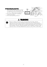
3.1 Method of transport 

·  When lifting the pump using a chain hoist or crane before transporting it, be sure to lift it by the 

specified lift point (see “1. Names of parts and materials”). 


                                      WARNING 

·  Be careful that nobody will pass under the pump when you lift it. It would be very 

dangerous if the pump should fall. 


                                      CAUTION 

·  See “10.1 Main specifications”. Remember that the pump is heavy, so extreme care must be 

taken when lifting it. 

·  When moving the pump with a forklift or truck, make sure that the pump will not fall. If it 

does, it may be damaged and/or cause bodily injury. 

·  NEVER try to move the pump by pulling the hose connected to the pump. The hose or the 

pump may be damaged. 


3.2 Installing the pump 

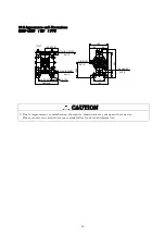
1)  Decide where the pump should be installed and secure a suitable 

space (see Fig.3.1 A to D). 


<NOTE> 

·  Try to keep the suction lift as short as possible. 

Protect diaphragm from abnormal breakage, inlet pressure must be 
kept below the following values: 
*PTFE diaphragm 


: 2.8 PSI (height 6.6 ft) During operation 

                                    : 7 PSI (height 16.4 ft) Not in operation 
*Other diaphragms


: 14 PSI (height 32.8 ft) 

  (When using clean water under ambient temperature) 

·  Remember to provide sufficient space around the pump for 

maintenance. 

·  The direction of the fluid intake port and the discharge port can be 

switched opposite from each other. (For switching, see the 
maintenance manual.) 

·   In the event diaphragm failure the exhaust from pump may contain 

some sludge. 
When operating the pump where it would have an impact on the 
environment, the exhaust should be directed to a place where there 
will be no environmental impact. 

 
2)  Remove the pump from the package and 

install it in the designated location. 

3)  When fixing the pump in place, use the 

cushions on the pump base, and secure the 
pump by tightening the tied-down bolts a 
little at a time. 


Fig.3.1 

Содержание DP-15 Series

Страница 1: ...Doc No NDP 456U 05 OPERATION MANUAL YAMADA AIR OPERATED DOUBLE DIAPHRAGM PUMP DP 15 series...

Страница 2: ...lypropylene Polyacetal polyvinylidene fluoride depending on the model you have selected according to the type of fluid to be pumped The diaphragms are made of rubber based or plastic based materials F...

Страница 3: ...e above may cause air pollution damage to the pump or even an explosion Pressure Ratings are dependent on pump material and liquid temperature variations Please see Temperature Pressure Curve in the 1...

Страница 4: ...upon the type of fluid being pumped bubbles of flammable gas may be generated Make sure that ventilation is satisfactory This product itself its piping and exhaust ports should be kept away from unsh...

Страница 5: ...erial is compatible with liquid being pumped or damage may result to the pump or product being pumped When working in the vicinity of pumping of fluid with this product be sure to wear protective gear...

Страница 6: ...n 13 5 2 Flow adjustment 13 5 3 Shutdown 14 5 4 Releasing the pressure 14 6 Method of cleaning 15 7 Daily check 16 8 Troubleshooting 8 1 Pump does not run 16 8 2 Pump runs but fluid does not come out...

Страница 7: ...DP 15FVT Polypropylene type FVT Polyvinylidene fluoride type Type FPN BPN FPT BPT BPH BPS FVT Switching Portion ADC12 Fluid contact Portion PPG PVDF Diaphragm NBR PTFE TPEE TPO PTFE Flat valve PTFE B...

Страница 8: ...ce drawings on 1 Names of parts and materials CAUTION All of the connection parts are capped or taped for shipment Remove the caps and tapes When installing accessories make sure that no foreign matte...

Страница 9: ...Try to keep the suction lift as short as possible Protect diaphragm from abnormal breakage inlet pressure must be kept below the following values PTFE diaphragm 2 8 PSI height 6 6 ft During operation...

Страница 10: ...provide protective measures installation of a pit or sensors etc in consideration of possible leakage of fluid and post warning signs at necessary places For details see the applicable operating cauti...

Страница 11: ...ires to the connected piping and any other connected equipment For details see the applicable operating caution on P 3 When the pump is operated without a ground wire or otherwise not properly grounde...

Страница 12: ...p to stop larger particles Otherwise such particles may cause a malfunction If depending upon the place of pump installation the volume of the pumped fluid changes drastically install a relief valve o...

Страница 13: ...port of the pump to supply enough air to run the pump The air compressor should be able to provide adequate air flow to the pump Attach the compressor as close as possible to the pump considering oper...

Страница 14: ...tion class 1 turbine oil equivalent ISO VG32 grade for lubricants Do not apply lubricants more than required and also do not use any other lubricants which designated on this instruction manual This m...

Страница 15: ...rloaded and this may cause damage such as bending of the center rod After finishing your work purge the remaining fluid from the pump see 6 Cleaning of cleaning 5 4 Releasing the pressure 1 Make sure...

Страница 16: ...h different hoses to the suction side and the discharge side for cleaning 4 Be ready with a vessel with cleaning solution select cleaning solution appropriate for the type of fluid pumped and then con...

Страница 17: ...and clean the fluid piping The pump is clogged with sludge Disassemble the casing check and clean 8 2 Pump runs but fluid does not come out Cause Action to be taken The suction lift or discharge head...

Страница 18: ...ssible diameter Disassemble the casing check and clean 8 7 Irregular vibration Cause Action to be taken The supply air pressure is too high Adjust the supply air pressure The spool oscillates and occu...

Страница 19: ...ess Limitation of Viscosity 0 5 Pa s or less Operating Temperature Range Temperature Ambient 0 70 C Temperature Liquid 0 60 C A weighted emission sound pressure level 4 85 dB A weighted sound power le...

Страница 20: ...UTLET LIQUID INLET AIR INLET EXHAUST FVT Rc1 2 Rc1 2 Rc1 4 Rc3 8 10 2 Appearance and dimensions DP 15FP BP FVT CAUTION Due to improvement or modification of products dimensions may change without noti...

Страница 21: ...instruments and procedure Fig 10 1 Conditions a Supplied air pressure Maintaining preset pressure b Liquid pumped Fresh water c Temperature Ambient d Condition of suction Flat suction 0 feet head e M...

Страница 22: ...n of the component parts of the product 4 Irregularity arising from repair made by other than by our firm our regional office dealer or authorized service personnel 5 Malfunction arising from modifica...

Страница 23: ...22 12 Warning symbols BEWARE HIGH TEMPERATURE ELECTRIC SHOCK POISON FLAMMABLE CORROSION EXPLOSION General warnings cautions and danger notifications FIRE STRICTLY PROHIBITED...

Страница 24: ......

Страница 25: ...FAX 31 0 74 242 1055 E mail sales yamada nl Web www yamada europe com Manufactured by YAMADA CORPORATION INTERNATIONAL DEPARTMENT 1 1 3 Minami Magome Ota ku Tokyo 143 8504 Japan PHONE 81 0 3 3777 0241...

Отзывы: