


10
Fig.16
air supply valve
rubber
At disassembly, even if one side seems to be broken, replace both left and right sides
simultaneously in respect of valve parts.
[NOTE] The anti-loosing wire cannot be reused. Do not use an alternative wire. Be sure to
replace the locking wire with a new one.
④
After removing the valve stem on the left and right sides, pull up the trip rod. Then,
peripheral parts including the reversing valve body can be disassembled as shown in the
illustration (Fig.14).
[NOTE]
If the trip rod is stretched too forcibly, its parts may be scattered by strong spring
force.
⑤
Check the air supply valve, discharge valve, and packing of the end of the valve shaft by
crushing and stretching. If even a small flaw is found, be sure to replace the
corresponding parts of both sides simultaneously.
⑥
At re-assembly, pay attention to the up/down direction of reversing bar. (Fig.16)
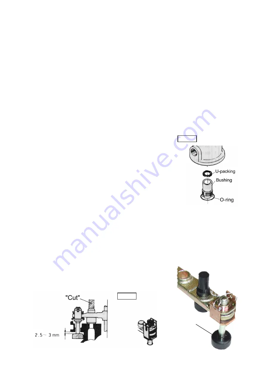
(4) Disassembling the Packing gland
①
Unscrew the and remove it from the lower part of the body.
The bushing and U-packing can be disassembled. (Fig.15)
(For the bushing , prepare a metal flat bar with a width of
about 45 mm and a thickness of about 3 mm, and insert it in
the notch of the bushing. Then, unscrew it for removal.)
②
Check the U-packing for abrasion. If necessary, replace it.
(5) Precautions on assembling the Reversing valve
Make an adjustment carefully by interposing a coin as a gauge so that the clearance between
the reversing valve and the piston may be 2.5 mm to 3 mm. It is important to finish both
left and right clearances with the same dimensions. (Fig.16)
①
Turn the groove of the valve stem with a bladed screwdriver to make an adjustment.
②
The groove of the valve stem should be at a right angle to the reversing bar because the
anti-loosing wire must be passed through it lastly.
③
To replace the discharge valve, cut it off with a cutter and insert a new discharge valve as
shown in the figure. (Be sure to replace two discharge
valves simultaneously. If a new part and the old part are
combined for use, a difference in rubber hardness has a
bad effect, resulting in a failure.)
Fig.15
Содержание 850097
Страница 17: ...12 5 5 Parts Disassembly Drawing and Parts List Parts Disassembly Drawing ...
Страница 21: ...MEMO ...