


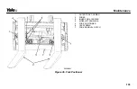


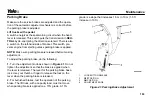


1.
FORK
2.
LOCK PIN
3.
SPRING
4.
WASHER
5.
WEDGE
6.
KNOB
7.
LOCK PIN ASSEMBLY
Figure 38. Fork Lock Pin Assembly
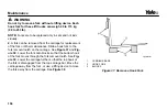
Forks, Inspect
1.
Inspect the forks for cracks and wear. Check that the
fork tips are aligned as shown in
. Check that the
bottom of the fork is not worn (Item 4 in
2.
Replace any damaged or broken parts that are used to
keep the forks locked in position.
Forks, Install
1.
Move the fork and carriage so that the top hook on the
fork can engage the upper carriage bar. Raise the carriage
to move the lower hook through the fork removal notch.
Slide the fork on the carriage so that both upper and lower
hooks engage the carriage. Engage the lock pin with a
notch in the upper carriage bar. See
.
2.
If lift truck is equipped with a fork positioner, install inner
fork carriers using four capscrews. Tighten capscrews to
35 N•m (25 lbf ft). See
Maintenance
157
Содержание VERACITOR GCC030VX
Страница 20: ...SEE THE PARTS MANUAL FOR THE PART NUMBER Figure 4 Warning and Safety Labels Sheet 2 of 3 Model Description 18...
Страница 21: ...SEE THE PARTS MANUAL FOR THE PART NUMBER Figure 4 Warning and Safety Labels Sheet 3 of 3 Model Description 19...
Страница 24: ...Figure 6 Display Switch Cluster Right Side Display Inputs Model Description 22...
Страница 40: ...Figure 8 Operator Controls Sheet 2 of 2 Model Description 38...
Страница 83: ...Figure 13 Seat Adjustment Full Suspension Operating Procedures 81...
Страница 115: ...1 DRIVE TIRES 2 STEERING TIRES Figure 17 Put a Lift Truck on Blocks Maintenance Schedule Maintenance Schedule 113...
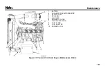
Страница 124: ...Figure 26 Yanmar 2 6L Diesel Engine Prior to January 2011 Maintenance and Lubrication Points Maintenance Schedule 122...
Страница 172: ...Figure 43 LPG Tank and Bracket Maintenance 170...


