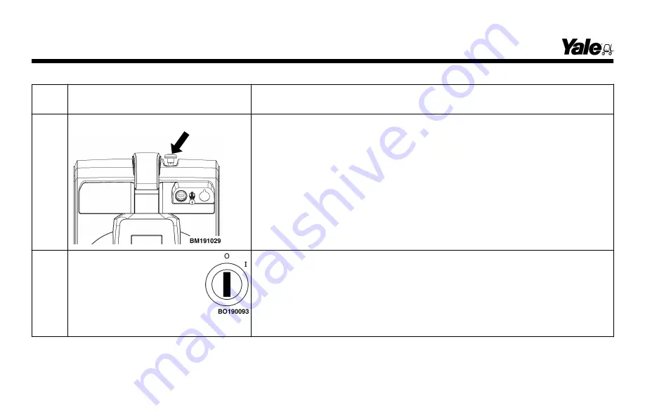
Table 1. Instruments and Controls (See Figure 5) (Continued)
Item
No.
Item
Function
3
Emergency Power Disconnect
The emergency power disconnect is located on top of the cowl. Push the
button to interrupt power supply.
4
Key Switch
The key switch is located on the operator's display panel. The key switch
has two positions: O and I. No truck functions are enabled when the key is
the O
(OFF)
position. When the key is rotated clockwise to the I
(ON)
posi-
tion, power is applied.
NOTE:
Always raise the control handle or delivery handle to the full upright
position and move the key to the
OFF
position when leaving the lift truck.
Model Description
24
Содержание MPB045VG
Страница 13: ...Figure 4 Warning and Safety Labels Model Description 11...
Страница 15: ...Instruments and Controls Figure 5 Instruments and Controls Model Description 13...
Страница 50: ...Figure 9 Putting the Lift Truck on Blocks Maintenance Schedule Maintenance Schedule 48...
Страница 51: ...Figure 10 Maintenance Points Maintenance Schedule 49...
Страница 63: ...1 LED 2 LABEL Figure 14 Charger LED s Maintenance 61...
Страница 69: ...1 CRANE 2 SPREADER BAR 3 INSULATOR STRAPS 4 BATTERY Figure 17 Changing the Battery Maintenance 67...
Страница 70: ...Figure 18 Battery Compartment Maintenance 68...
Страница 74: ...NOTES 72...
Страница 75: ...Spacer 3 19 2 19 7 18 5 16 1 16 5 14 12 13...


