DISASSEMBLY
Care must be exercised in disassembly of the
hoist to assure proper assembly. The following
pins have tapered splines and can only be
removed by tapping on the end opposite the
splined grooves.
Lower Hook Block, Upper Hook Collar
and Dead End Pins
When removing or installing the Lower Hook
Block Pins (646-29J or 646-129J) on the 1/4 thru
2 ton units, the Upper Collar Pins (646-1E or 646-
101E) on the 1/4 thru 2 ton units and the Dead
End Pins (646-259) on the 3, 4, 8 and 10 ton units,
care must be taken so as to prevent damaging
the pin and/or the part into which the pin is driven.
These pins are tapered groove pins and as a
result, they can only be removed and installed in
one direction. To remove the pin, a drift and
hammer (or slow acting press) are required. For
the lower hook block pins, a V-block will also be
necessary. The drift should be the same diameter
as the pin (5/16” diameter for the 1/4 thru 1 ton
units and 7/16” diameter for the 1-1/2, 2, 3, 4, 8
and 10 ton units) and it should be placed on the
small end of the pin. The small end of the pin is
the end opposite the end on which the 3 grooves
are visible. Place the drift on the small end of
the pin and drive the pin out using a hammer or
slow acting press. When removing the pin from
the lower hook block, the hook block should be
placed in a V-block.
To re-install the pin, the parts must be arranged
the same as they were when the pin was
removed. To do this, use the small end of the pin
as a gauge. After it is determined which end of
the hole is the largest, arrange the parts so that
the large holes are aligned and insert the small
end of the pin into the hole. Push the pin in by
hand until it stops and then use a hammer or
slow acting press to drive the pin into position
so that the end of the pin is flush with the
outside surface of the hook block body, upper
hook collar or hoist hanger.
Using other than the Yale supplied, high
strength pins may cause the pin to break and
allow the hoist and/or load to fall.
To Avoid Injury:
Use only the special high strength pin as
supplied by Yale.
ASSEMBLY
Consideration must be given to the following
when assembling the hoist:
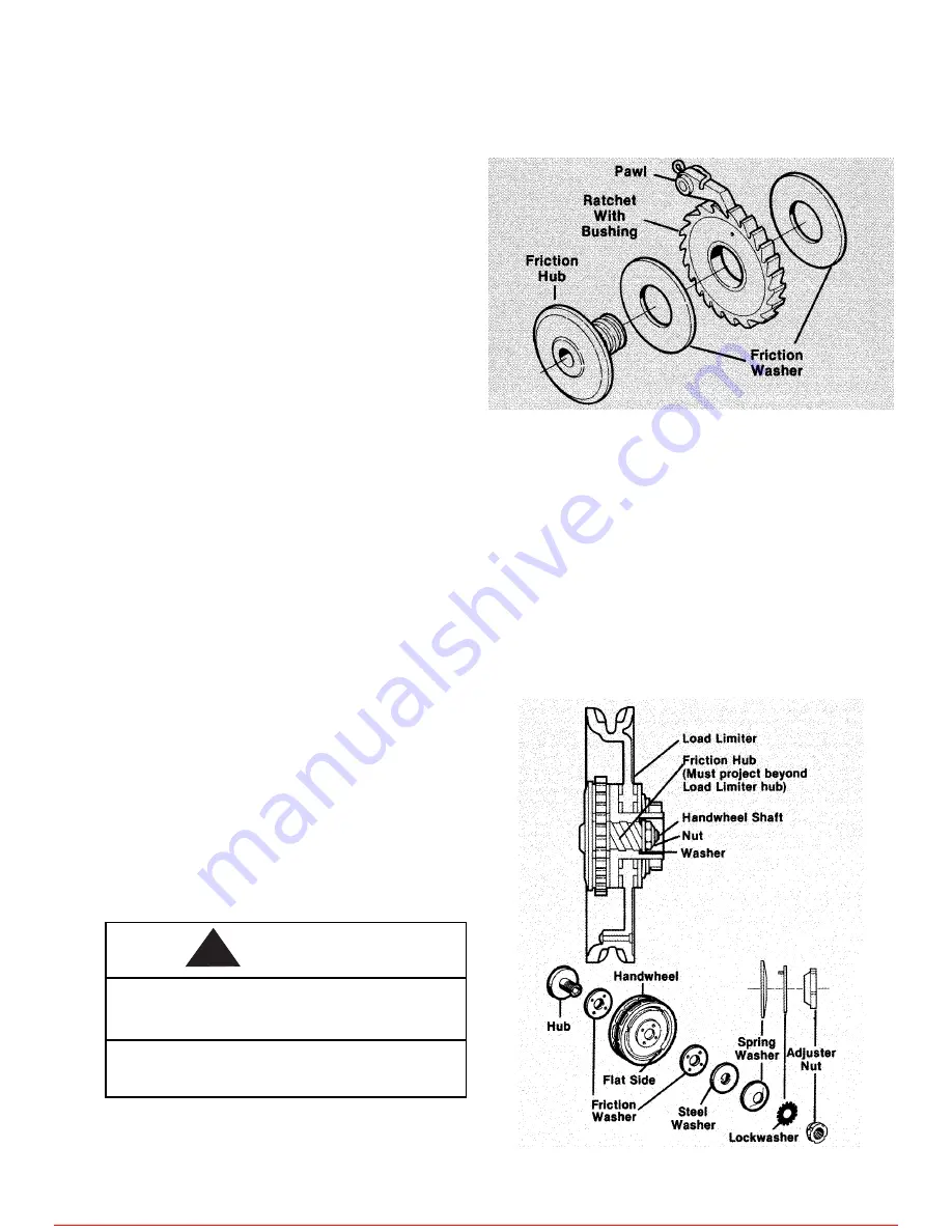
Brake.
Assemble the brake components per Figure 10.
Check the ratchet to be sure the bushing is flush with
or below the surface on both sides. When installed, the
teeth must face as shown in Figure 10 and engage the
pawl. Do not lubricate. The brake operates dry.
FIGURE 10. Brake Assembly
Load Limiter.
Place a small amount of stay-put lubri-
cant such as Moly-Duolube Style 69 (Hercules Packing
Co.) on Load Limiter handwheel threads to lubricate
the friction hub at assembly. Do not allow lubricant to
contact brake surfaces or friction surfaces of Load
Limiter.
The handwheel shaft nut and washer must tighten
against the friction hub, not the Load Limiter (see
Figure 11). the Load Limiter must be free to revolve
slightly on the friction hub. If the Load Limiter is
disassembled, it must be recalibrated before being
placed in service.
FIGURE 11. Load Limiter Assembly
8
WARNING
!
For more information contact: Sievert Crane and Hoist, (708) 771-1600, [email protected], www.sievertcrane.com


