


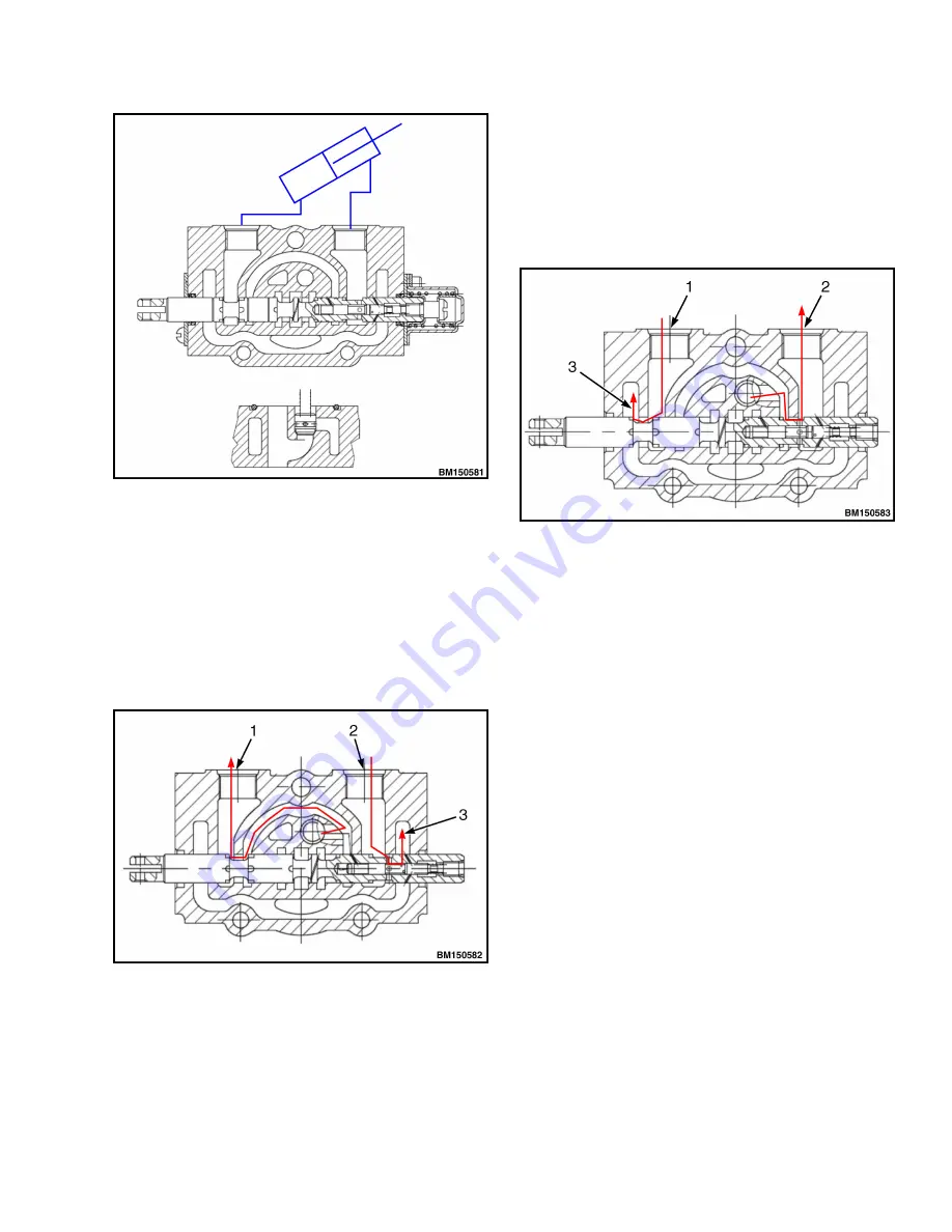
Figure 38. Spool Valve Neutral
Spool Valve (Pushed In):
When the valve is pushed in, the middle channel is
closed while the fluid from the inlet port opens the one-
way valve. The fluid flows to the interface B of the
cylinder (item 1, Figure 39), while the fluid from
cylinder interface A (item 2, Figure 39) flows to the
tank through low-pressure channel (item 3, Figure 39).
A return spring returns the valve to NEUTRAL position.
1. FLUID FROM TILT CYLINDER INTERFACE B
2. FLUID TO TILT CYLINDER INTERFACE A
3. RETURNING TO FLUID TANK
Figure 39. Push-in Spool Valve
Spool Valve (Pulled out):
When neutral position is closed, the hydraulic oil from
the inlet port opens the one-way valve and flows to the
cylinder interface A, (item 2, Figure 40) while the oil
from cylinder interface B (item 1, Figure 40) flows to
the tank through low-pressure channel. A return spring
returns the valve to NEUTRAL position.
1. FLUID TO CYLINDER INTERFACE B
2. FLUID FROM TILT CYLINDER INTERFACE A
3. RETURNING TO FLUID TANK
Figure 40. Pull-out Spool Valve
Primary Relief Valve and Priority Spool
Reference Figure 41
The primary relief valve is composed of the two parts,
a main valve and pilot valve. When multi-way valve is
reversed, the high-pressure oils in cavity (P) and
working mechanisms (such as lift cylinder and tilt
cylinder) are connected, the pressurized oil acts on the
pilot valve, through the fixed throttle holes. When
system pressure is larger than the system regulated
pressure, the pilot valve opens, The valve core of the
entire main valve (A) moves rightwards, for the
pressurized oil to be directly connected with low-
pressure channel (G), for cavity for the pressure in
cavity P to lower, in order to ensure the stability of
system pressure. Adjusting screw H on the primary
relief valve will increase or decrease the system
pressure.
The priority spool is in a spool and spring set up. It is
used to divert oil to the Steering Control Unit (SCU)
first and then actuates, to divert oil to provide hydraulic
oil to the hydraulic valve for Mast functions. When the
steering wheel is rotated, the oil cavity (M) is
connected with high-pressure oil circuit. When system
pressure is greater than spring pressure, the valve
8000 YRM 2199
Hydraulic System
43
Содержание A7S1
Страница 4: ......
Страница 7: ...TABLE OF CONTENTS Continued Lubrication System 83 PDM Schematics 85 Table of Contents iii ...
Страница 8: ......
Страница 36: ...Figure 25 2 2 5T Wheel Brakes Brake System 8000 YRM 2199 28 ...
Страница 54: ...Figure 43 Oil Circuit of Hydraulic System Hydraulic System 8000 YRM 2199 46 ...
Страница 66: ...Figure 57 Hydraulic Schematic Diesel and Gasoline Forklift Trucks Hydraulic System 8000 YRM 2199 58 ...
Страница 69: ...Figure 58 Two Stage Free Lift and Three Stage Masts 8000 YRM 2199 Lifting System 61 ...
Страница 76: ...Figure 61 With NISSAN engine K21 K25 Sheet 1 of 2 Electrical System 8000 YRM 2199 68 ...
Страница 77: ...Figure 62 With NISSAN engine K21 K25 Sheet 2 of 2 8000 YRM 2199 Electrical System 69 ...
Страница 78: ...Figure 63 With PSI engine Sheet 1 of 2 Electrical System 8000 YRM 2199 70 ...
Страница 79: ...Figure 64 With PSI engine Sheet 2 of 2 8000 YRM 2199 Electrical System 71 ...
Страница 80: ...Figure 65 With Mitsubishi engine S4S Sheet 1 of 2 Electrical System 8000 YRM 2199 72 ...
Страница 81: ...Figure 66 With Mitsubishi engine S4S Sheet 2 of 2 8000 YRM 2199 Electrical System 73 ...
Страница 82: ...Figure 67 With Xinchai engine Sheet 1 of 2 Electrical System 8000 YRM 2199 74 ...
Страница 83: ...Figure 68 With Xinchai engine Sheet 2 of 2 8000 YRM 2199 Electrical System 75 ...
Страница 84: ...Figure 69 With Yanmar engine 92 98 Sheet 1 of 2 Electrical System 8000 YRM 2199 76 ...
Страница 85: ...Figure 70 With Yanmar engine 92 98 Sheet 2 of 2 8000 YRM 2199 Electrical System 77 ...
Страница 86: ...Figure 71 With Yanmar engine 94 Sheet 1 of 2 Electrical System 8000 YRM 2199 78 ...
Страница 87: ...Figure 72 With Yanmar engine 94 Sheet 2 of 2 8000 YRM 2199 Electrical System 79 ...
Страница 88: ...Figure 73 Optional Accessories Electrical System 8000 YRM 2199 80 ...
Страница 93: ...PDM Schematics 8000 YRM 2199 PDM Schematics 85 ...
Страница 94: ......
Страница 95: ...8000 YRM 2199 Figure 76 PDM Suitable For All Engines 87 88 blank ...
Страница 96: ......
Страница 97: ...8000 YRM 2199 Figure 77 PDM With OPS Suitable For All Engines 89 90 blank ...
Страница 98: ......
Страница 99: ......
Страница 100: ...8000 YRM 2199 1 21 10 20 11 19 10 19 5 19 ...


