Page 15
recommended on air motors. See paragraph 7-2.e. For any
other repairs the air motor should be returned for factory
servicing.
(4) Lubricate motor with small amount of Air Hoist Motor Oil
or good grade 1OW machine oil (approximate viscosity 150
SSU at 100°F.). Mufti-viscosity, detergent type engine oil is
not recommended.
c. Assembly of Control Head. At reassembly of control head
and throttle valve, observe these precautions:
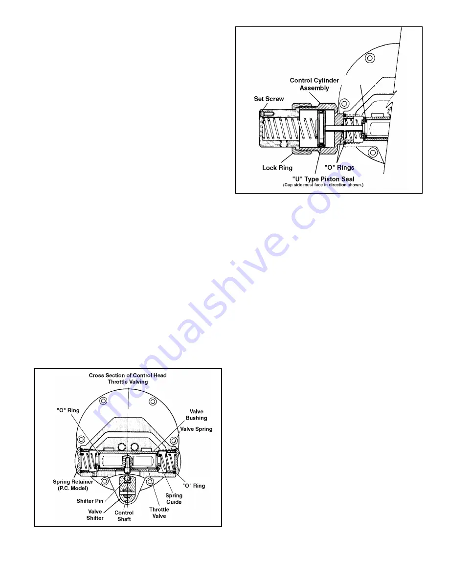
(1) Lightly oil throttle valve and bushing with S.A.E. 20 oil. If
shifter pin was removed from valve, assemble valve with
threaded hole facing slot at bottom of bushing in housing
(Figure 7-13). Shifter pin should be assembled with LOCTITE.
Extreme care must be taken not to get any LOCTITE on valve
outside diameter since this will lock up valve and scrap the
complete head assembly.
Note: Apply lubricating oil to “0” rings and “U” seals
before installing and take care during installation so as
not to cut, pinch, or otherwise damage them.
(2) Use new “0” ring seals at each end of valve. Install spring
guides and valve springs in bores on each side of housing
and secure with spring retainer (pull cord models) or control
cylinders (pendant throttle control models). Use new “0” ring
gaskets.
(3) At reassembly of control cylinders (pendant throttle
control models), use new “U” type seals on piston heads and
“0” ring seals on piston stems. Be sure “U” type seals face
direction illustrated in Figure 7-14.
(4) Use new “0” ring gaskets on adjusting screws. When
installing screws in control head housing, turn them in until
heads are flush or slightly below face of housing. Adjustment
is accomplished during testing of hoist, paragraph 2-4.
(5) At reassembly of screen and air inlet swivel, install a
new “0” ring seal inside swivel bushing.
(6) In mounting control head housing on hoist, use a new
motor-to-head air seal gasket and a new head-to-frame gasket.
d. Assembly of Brake. If the brake linings show excessive
wear, replace brake shoes. In reassembling the brake, the brake
wheel assembly goes into position first and is fastened in place
by the four screws referred to in paragraph 7-2.f.(1). (See Figures
7-8 and 7-9.) Now place the steel fulcrum balls in their receiving
cup, using a small amount of thick grease to hold them in place.
The balls should retract completely into the receiving cups. Now
place the shoes up to the fulcrum balls and brake wheel.
Replace the brake spring, using the spreader tool to start the
spring over the shoes. (See Figures 7-4 and 7-5.) Tap the spring
into place. Adjust brake shoes per instructions in Figure 7-15.
Figure 7-13. Section View Showing Assembly of
Throttle Valve, Springs and Valve Shifter
in Control Head.
12001
Figure 7-14. Section View Showing Assembly of Control
Cylinder on Control Head (Pendant Throttle Control Models).
12002A


