

The RF
μ
TUNING KIT provides ultra-sharp RF selectivity for the front end of the transceiver. Very high Q is made possible by the
narrow-band design. Three RF
μ
TUNING KITS are available. The MTU-160 covers the 1.8 MHz band. The MTU-80/40 covers the 3.5
and 7 MHz bands. The MTU-30/20 covers 10.1 and 14 MHz bands.
When any (or all) of the three optional units are installed, they will be automatically adjusted to center on your operating frequency.
The narrow bandwidth is especially useful on the low bands, when many strong signals are being received via NVIS propagation (Near
Vertical-Incidence Signals) within a narrow bandwidth. The added protection for the RF stage is especially helpful in preventing IMD
and blocking.
The RF
μ
TUNING KIT, provides a Q and shape factor much higher than that afforded even by VRF. It can also be manually adjusted to
provide relief from interference as close as 10 kHz away. The insertion loss of the RF
μ
TUNING KIT is higher than that of the VRF
circuit, so if Noise Figure is a concern you may select the VRF circuit, instead of RF
μ
TUNING KIT, via the Menu of the
FT-2000
transceiver.
1
. Press the [
VRF
] button momentarily. The “
” icon will appear at
the FLT column of the Receiver Configuration Indicator on the FT-
2000 display, and the
μ
-Tune circuit will be engaged.
The
μ
-Tune circuit will
automatically align itself
to your operating fre-
quency.
The VRF circuit will engage when you choose an amateur band
which is not connected to a
μ
-TUNE UNIT.
2
. Now rotate the [
VRF
] knob to peak the response (background noise) or
reduce interference.
You may observe the relative peak point
of the
μ
-Tune filter in the Tuning Offset
Indicator on the display while tuning the
[
VRF
] knob.
The amount of change in the center fre-
quency of the
μ
-Tune filter, when rotat-
ing the [
VRF
] knob by one click, can be configured using Menu
item “
035 GEnE
μ
T DIAL
035 GEnE
μ
T DIAL
035 GEnE
μ
T DIAL
035 GEnE
μ
T DIAL
035 GEnE
μ
T DIAL
.”
3
. Press the [
VRF
] button (momentarily) once more to disengage the
μ
-
Tune filter. The “
” icon will turn on in place of “
” icon. In this
mode, only the fixed bandpass filter for the current band will be en-
gaged.
Q
UICK
N
OTE
The permeability-tuning concept utilized in the
μ
-Tune
circuit dates back many decades, as it was incorporated
in such classic transceivers as the
FT-101
and
FT-901
series, in addition to the
FT
DX
401
and similar models.
The
μ
-Tune circuit in this RF
μ
TUNING KIT is the high-
est development of this circuit concept ever employed
in an Amateur transceiver, and is adopted in our high-
est-grade transceiver
FT
DX
9000
series.
µ-T
UNE
AND
VRF: C
OMPARISONS
TO
F
IXED
B
ANDPASS
F
ILTERS
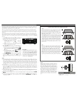
µ-Tune Filter is activated
µ-Tune
Inspection of the illustrations to the right will demonstrate the profound
advantage of the
μ
-Tune circuit. In illustration [
A
], the gray area repre-
sents the passband of a typical fixed bandpass filter covering the 1.8 ~ 3
MHz range; this is typical of the kind of bandpass filter found in many
high-quality HF receivers today. Note also the hypothetical distribution of
signals across the 160-meter band.
In illustration [
B
], note the narrow white segment within the gray passband
of the fixed BPF. These narrow segments represent the typical bandwidth
of the
μ
-Tune filter, and one can see that the passband has been reduced
from about 750 kHz in the case of the fixed BPF) to a few dozen kHz when
μ
-Tune is engaged. The vast majority of the incoming signals are outside
the passband of the high-Q
μ
-Tune filter, and they will not impinge on any
of the RF/IF amplifiers, the mixers, or the DSP. Very strong out-of-band
signals like this can cause Intermodulation, blocking, and an elevated noise
floor for a receiver.
A
DVICE
With
μ
-Tuning, the center frequency of the filter is continuously
adjustable throughout its operating range. The quality L/C com-
ponents ensure high Q of the circuit and a tight passband. The
RF preselection design task required the selection of quality L/C
components, but the crafting of a tuning mechanism and tuning
concept that preserves system Q while providing consistent
smooth automated tuning over a wide operating frequency range.
The smooth tuning is achieved by varying the inductance over a
wide range; this is accomplished by motor-driving a large 1.1”
(28 mm) ferrite core stack through a 2” high (50 mm) coil struc-
ture. The Q of the
μ
-Tune circuit is over 300, and yields un-
matched RF selectivity for outstanding rejection of undesired sig-
nals.
A
B
a
b
14.5MHz
22MHz
FRONT-END BAND WIDTH
14.5MHz
22MHz
VRF BAND WIDTH
1.8MHz
2.5MHz
μ
TUNE BAND WIDTH
1.8MHz
2.5MHz
FRONT-END BAND WIDTH
VRF
In this example, illustration [
a
] depicts a typical fixed bandpass filter cov-
ering 14.5 to 22 MHz, and once again the gray shaded area depicts the
fixed bandpass filter’s frequency coverage. The vertical lines in the illus-
tration represent hypothetical signals throughout this frequency range.
Figure [
b
] shows the same fixed BPF, with the white area representing the
typical passband of the VRF filter operating in the same frequency range.
Although the selectivity of the VRF is not as tight as that of the
μ
-Tune
filter, the RF selectivity of the VRF preselector is still magnitudes better
than that of the usual fixed bandpass filter, affording significant protection
against the ingress of high signal voltage from strong out-of-band signals.
[VRF] button
[VRF] knob
“VRF” icon
Main Tuning Dial knob
Tuning Offset Indicator
A
DVICE
The
μ
-Tune filters are the most advanced, selective RF preselector filters ever incorporated into an Amateur Radio transceiver. The
RF selectivity provided by
μ
-Tune can be of tremendous value in ensuring quiet, intermod-free reception even in the most crowded
bands on a contest weekend. The
μ
-Tune filters provide RF selectivity on the order of a few dozen kHz at -6 dB, at the expense of
a few dB of system gain on bands where noise figure is seldom an issue. You will notice that the S-meter deflection, when
μ
-Tune
is engaged, is slightly less than when it is out of the circuit. This is normal. If your antenna system gain is so low that it is impossible
to hear band noise when
μ
-Tune is engaged (highly unlikely), just switch it out or revert to the VRF system, which has slightly less
insertion loss.
As you tune around on an amateur band with
μ
-Tune engaged, the microprocessor automatically commands the stepper motor to
drive the toroid core stack and center the filter on your current operating frequency (the tuning resolution is 5 kHz). You may,
however, use the [
VRF
] knob to skew the filter response to one side or the other of your operating frequency, to deal with heavy
interference on either side. To re-center the
μ
-Tune filter on the operating frequency, and eliminate any offset, press and hold in the
[
VRF
] switch for two seconds.
You can use the
μ
-Tune circuit on the Sub Band Receiver (VFO-B). However, in this case, the stepper motor does not drive the
toroid core to center the filter on your operating frequency. You must adjust the peak response (background noise) or reduce
interference by rotating the [
VRF
] knob.
You may always observe the peak point of the
μ
-Tune filter in the Tuning Offset Indicator on the display via Menu item “
010 diSP
010 diSP
010 diSP
010 diSP
010 diSP
BAR SEL
BAR SEL
BAR SEL
BAR SEL
BAR SEL
.”
While
μ
-Tune is a superior RF preselection circuit, it may be disabled via the Menu on the
FT-2000
; if this is done, the VRF circuit
will engage when the [
VRF
] button is pressed. To disable
μ
-Tune, enter the Menu item “
035 GEnE
μ
T DIAL
035 GEnE
μ
T DIAL
035 GEnE
μ
T DIAL
035 GEnE
μ
T DIAL
035 GEnE
μ
T DIAL
” of the
FT-2000
then
set the selection to “OFF.”
O
PERATION
45-60 MHz
9.9-13.9 MHz
13.9-20.9 MHz
4.7-6.9 MHz
1.7-2.5 MHz
20.9-30.1 MHz
6.9-9.9 MHz
3.4-4.7 MHz
バンドパスフィルター
1
2
アンテナ
ア
ン
テ
ナ
セ
レ
ク
タ
ー
VRF
THRU
Antenna Selector
Antenna
Bandpass Filter
Top Band Edge
Bottom Band Edge
S
PECIFICATIONS
Case Size
(WxHxD): 4.7” x 5” x 12.9” (120 x 127 x 328 mm)
Weight
(Approx.):
5.7 lbs (2.6 kg)


