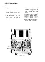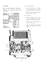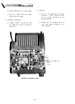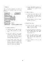
A. PLL Unit
1 ) VCV (Varactor Control Voltage)
a) With the dummy load connected to
the ANT jack, connect the DC
voltmeter (10V scale) to the VCV
terminal on the VCO Unit.
b) Tune the transceiver to 430 MHz
(432 M H z for Version D), and
while receiving, adjust TC301 on
the VCO Unit for at least 0.8V
(1.0V for Version D).
c) R e t u n e the transceiver to the
f r e q u e n c y indicated below and
a d j u s t TC301 again, this time
while transmitting, for the voltage
indicated.
d) Repeat steps b and c several times,
and then remove the voltmeter.
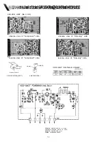
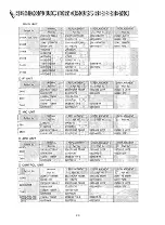
PLL ALIGNMENT POINTS
24
Содержание FT-712RH
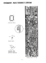
Страница 4: ...PA UNIT APC UNIT 430 VCO UNIT LCD UNIT CONTROL UNIT BOARD LAYOUT 2...
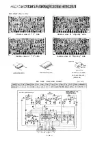
Страница 8: ...reverse view of chip only side 6...
Страница 9: ...MAIN UNIT VOLTAGE CHART DC VOLTS MAIN UNIT 1C VOLTAGE CHART DC VOLTS...
Страница 15: ...20 32 HD404418A01F 02003 obverse view of 1C side 14...
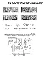
Страница 16: ...S obverse view of 1C side 15 ANODE 1 CATHOOE 1...
Страница 17: ......
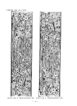
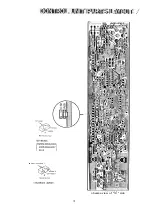
Страница 18: ...PA UNIT No 7 XX obverse view of component side reverse view of component side 17...
Страница 19: ...obverse view of chip only side reverse view of chip only side 18...
Страница 20: ...19...
Страница 21: ...MAIN UNIT 20...
Страница 22: ...21 e s A...
Страница 23: ...22...

