Xylem McDonnell & Miller PSE-800-M Скачать руководство пользователя страница 9

Installation

Determine location for the probe installation

DANGER:

Electrical hazard sufficient to kill. Always disconnect and lock out the power before you
service the unit.

NOTICE:

• Low water cut-off must be installed in series with all other limit and operating controls

on the boiler. Check for proper operation of all of the limit and operating controls
before leaving the site.

• All work must be performed by qualified personnel trained in the proper application,

installation, and maintenance of plumbing, steam and electrical equipment or systems
in accordance with all applicable codes and regulations.

Use the following criteria to locate a suitable position to install the probe .

• Install probe in a tapping on the boiler that is designated by the boiler manufacturer.

Review boiler IOMs or contact manufacturer for location of tapping.

• Probe must be installed below the location or level of the existing automatic reset low

water cut-off (LWCO). Installing the probe above this location could result in nuisance
shutdowns or lockouts.

• Install probe in a location above the minimum safe water level as designated by the

boiler manufacturer.

• Installing the probe in a location other than a tapping designated by the boiler

manufacturer could result in nuisance shutdowns of the burner.

• There must be at least 1/4 in of clearance between the end of the probe and the wall of

any piping or fitting.

• Do not install the probe in any pipe extension that covers all or part of the probe rod.

Water that is retained in a pipe extension and touches the probe prevents the probe
from recognizing a low water condition. The burner will not shut off.
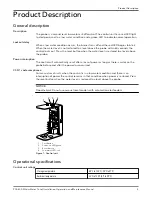
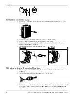
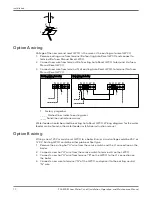
Install the probe

1. Apply a small amount of pipe sealant to the external threads (2) of the probe (1).

IMPORTANT: Do not use PTFE tape. Only use a pipe sealant.

1

2

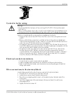
2. Tighten the probe (1) into the tapped connection (3) to 47 ft·lb (64 N·m).

Be sure to align the probe so that the mounting screws (4) are in a horizontal position.

Installation

PSE-800-M Low Water Cut-off Installation, Operation, and Maintenance Manual

7

Содержание McDonnell & Miller PSE-800-M

Страница 1: ...PSE 800 M Low Water Cut off Installation Operation and Maintenance Manual...

Страница 2: ......

Страница 3: ...all the control housing 8 Wire the probe to the control housing 8 Control to boiler wiring 9 Electrical conduit connections 9 Wire connections to the terminal block 9 Option A wiring 10 Option B wirin...

Страница 4: ...uipment or use of parts not provided by Xylem If there is a question regarding the intended use of the equipment please contact a Xylem representative before proceeding This manual clearly identifies...

Страница 5: ...ing specific symbol Electrical Hazard These are examples of other categories that can occur They fall under the ordinary hazard levels and may use complementing symbols Crush hazard Cutting hazard Arc...

Страница 6: ...d in this manual The monitoring equipment incorporated in the product is correctly connected and in use All service and repair work is done by Xylem authorized personnel Genuine Xylem parts are used O...

Страница 7: ...loss of power as long as there is water on the probe before and after the power loss occurred CSD 1 code compliance For manual reset units when the control is in a low water condition and there is an...

Страница 8: ...specifications Ratings Model Control Voltage Motor Switch rating Pilot rating PSE 802 M 24 24 VAC N A 50 VA PSE 802 M U 24 PSE 801 M 120 120 VAC 7 5 FLA 43 2 LRA 125 VA PSE 801 M U 120 Hertz 50 60 Con...

Страница 9: ...et low water cut off LWCO Installing the probe above this location could result in nuisance shutdowns or lockouts Install probe in a location above the minimum safe water level as designated by the bo...

Страница 10: ...ads 5 Tighten the mounting screws to approximately 2 ft lbs 2 6 N M Steps 2 and 3 Steps 4 and 5 4 6 4 6 Wire the probe to the control housing 1 Slip the ring terminal 7 followed by the lock washer 8 o...

Страница 11: ...the new manual reset LWCO turns off when the existing auto reset LWCO detects a low water condition reducing the chance of nuisance lockouts The water feeder continues to operate because there is stil...

Страница 12: ...lines indicate new wires Water feeder should be wired to existing Auto Reset LWCO Wiring diagrams for the water feeder can be found in the water feeder installation instruction manual Option B wiring...

Страница 13: ...a Model 67 LWCO Voltage of the new manual reset LWCO must be the same voltage as the burner circuit 1 Remove existing wire from terminal 1 of the Model 67 LWCO and connect it to Terminal B of the new...

Страница 14: ...2 3 4 N H C W B 1 1 2 3 4 TOP 2 3 4 1 Factory jumper bar 2 To burner 3 Neutral 4 Hot _ _ _ _ Dashed lines indicate existing wires _____ Solid lines indicate new wires Installation 12 PSE 800 M Low Wa...

Страница 15: ...he boiler a The burner turns off and the Red light begins to flash when there is no water on the probe b After 60 seconds the red light will stop flashing and will remain on IMPORTANT If water returns...

Страница 16: ...r cut off annually Remove and inspect the self cleaning probe every five years Use a non abrasive cloth and rinse with clean water when the probe requires cleaning Do not use sharp instruments to remo...

Страница 17: ...specified in the wiring diagrams of the boiler manufacturer or in this instruction manual 3 Check to ensure that PTFE tape has not been used on the threaded connection of the electrode to the boiler 4...

Страница 18: ......

Страница 19: ......

Страница 20: ...150 countries we have strong long standing relationships with customers who know us for our powerful combination of leading product brands and applications expertise backed by a legacy of innovation F...

Отзывы: