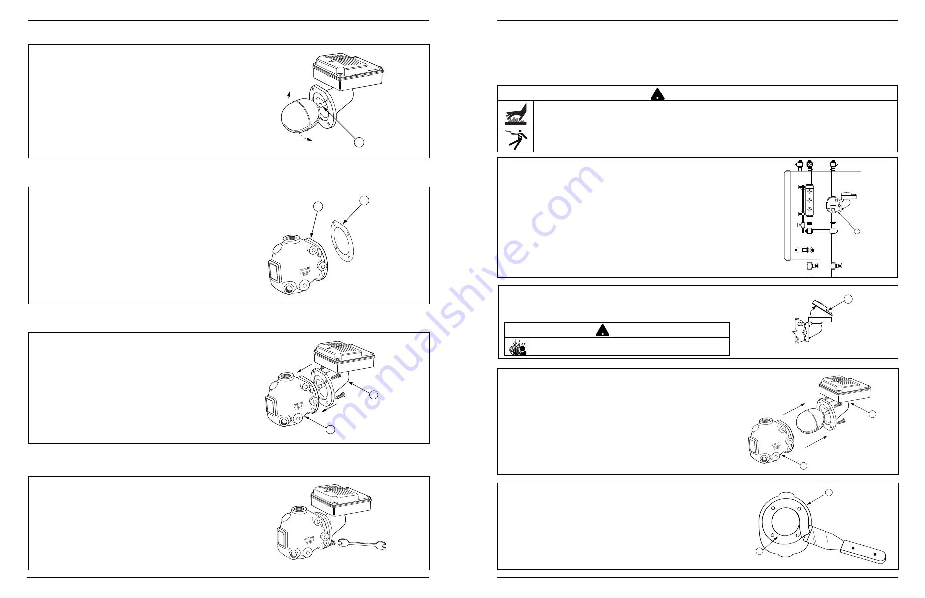
d.
Using a wrench, insert the four (4) bolts and
tighten them to approximately 14-20 ft•lb
(19-27 N•m) in an alternating star pattern.
G
F
H
b.
Align the bolt holes of the new head gasket
(H) on the sealing surface (F) of the control
body.
a.
Carefully remove the new replacement head
mechanism from the carton. Handle it carefully
to prevent damage to the float rod (G).
J
D
c.
Install the new replacement head (J) on the
body (D) by guiding the float into the control
body and aligning the bolt holes.
STEP 2 - Installing the Replacement Head Mechanism
4
3
A
B
C
D
c.
Remove the existing head mechanism (C)
from the body (D).
a.
Drain water in the boiler to a level which is
below the float chamber (A). Allow the boiler
to cool to 80˚F (27˚C) and release the boiler
pressure to 0 psi (0 bar).
b.
Using a flathead screwdriver, remove the junction
box cover (B). Disconnect, mark, and remove the
supply wires and conduit connections.
F
E
d.
Using a scraper, remove the old gasket (E).
Clean all debris from the float chamber. The
gasket sealing surface (F) must be smooth
and clean.
STEP 1 - Preparation
INSTALLATION –
TOOLS NEEDED:
One (1) pipe wrench, one (1) flathead screwdriver, one (1) scraper, and one (1) 9/16" socket or wrench.
• To prevent serious burns, the boiler must be cooled to 80˚F (27˚C) and the pressure must be 0 psi (0 bar)
before servicing.
• To prevent electrical shock, turn off the electrical power before disconnecting or making electrical connections.
Failure to follow this warning could cause property damage, personal injury or death.
!
WARNING
There may be more than one source of power to the boiler.
!
CAUTION


