


6
3
5
6
4
2
1
seat smoothly against the valve cage. Lift the outer edges
of each valve to make certain there is no debris lodged
under any valve. If there is debris lodged under any of the
valves, it will cause a diminished flow rate or loss of flow
entirely. If the valves do not seat smooth ly against the
valve cage, the valve cage assembly should be replaced.
If the pump has been leaking, the diaphragm must be
replaced. Remove the four phillips head diaphragm
retainer screws and mushroom shaped diaphragm
retainer caps. Remove the diaphragm and diaphragm
housing from the motor and wobble plate housing.
Inspect the wobble plate bearing to make certain it is not
corroded and still rotates smoothly.
With the new diaphragm positioned in the diaphragm
housing (ensure the raised sealing beads face outward
away from the motor) hold it against the wobble plate
with the four re tain ing cap holes aligned with the wobble
plate sockets. Push each diaphragm retainer cap
through the diaphragm and into the socket of the wobble
plate. Secure each retaining cap to the wobble plate with
a 1" phillips head retainer screw. Place the motor on its
rear end bell and position the valve cage against the
diaphragm ensuring each cavities seal groove is seated
on its sealing bead molded into the diaphragm. Ensure
the O-ring seal that separates the pumps intake chamber
from the dis charge chamber is properly seated in the ID
of the raised lip around the central discharge valve. While
holding the port retainer clips in their slide grooves in the
pump body, po si tion the body on the diaphragm and
inside the wobble plate housing. Secure the pump body
to the wobble plate housing with the four 2-1/4" ma chine
screws and flat washers.
Reinstall the pump to its mounting surface with four
fasteners through the rubber grommets. Ensure the seal-
ing O-ring is properly positioned on each port fitting and,
with the retaining clips slid back, push each port fitting
into its re spec tive socket. Slide each port retainer clip
forward until it snaps securely into its seated position.
Reconnect the orange motor lead to the positive supply
wire and the black motor lead to the negative wire.
Ensure the inlet seacock is open before re stor ing power
to and operating the toilet.
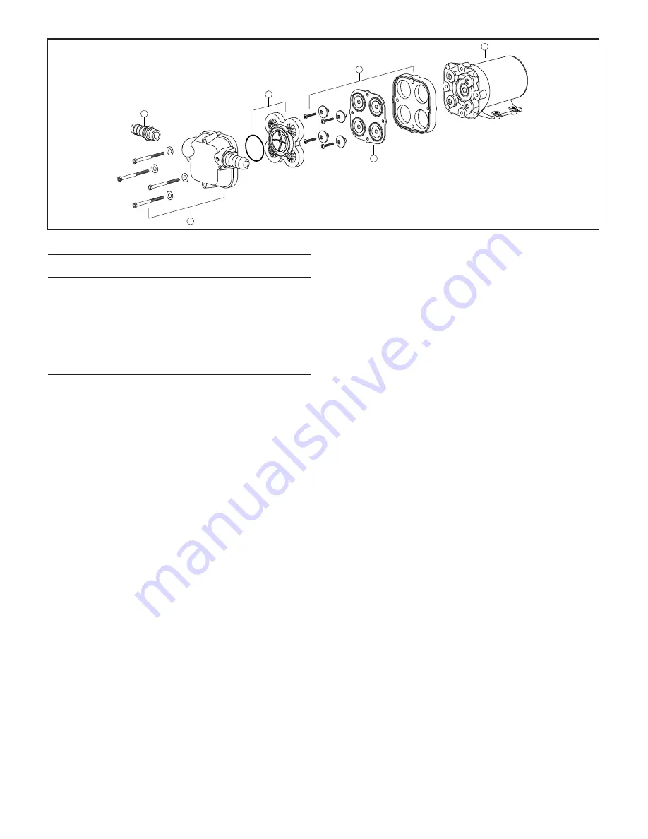
EXPLODED VIEW
PARTS LIST
Qty.
Part
Key
Description
Req.
Number
1
Port Kit (1 pair)
1
30653-1004
2
Body Kit
1
30608-1001
3
Valve Cage / Valve Assembly
1
30613-1001
4
Diaphragm Kit
1
30617-1000
5
Diaphragm Housing &
Retainer Cap Kit
1
30682-1000
6
Motor Kit 12 Vdc EMC
1
18753-0577
Motor Kit 24 Vdc EMC
1
18753-0578
PAR-MAX SERVICE INSTRUCTIONS
The PAR-MAX rinse water supply pump needs no periodic
maintenance for proper per for mance. The only time
service work should need to be performed on the pump is
if it should begin to leak water, suddenly delivers less
water than normal or should stop pumping al to geth er.
Should the pump begin to leak water, it will be necessary
to replace the diaphragm. If the pump delivers a reduced
rate of flow from normal or stops pumping altogether, it
will be necessary to either remove debris from the pump’s
flapper valves or replace the valve cage as sem bly.
NOTICE: Before performing any service, turn off the
electrical power to the toilet and rinse water pump. Take
precaution to ensure it is not turned on until service is
complete. Close the inlet fitting seacock.
It is generally easiest to remove the pump from its
installed position so that the service can be per formed on
a work bench. To do this, dis con nect the electrical wires
from the motor wire leads. Push the port retainer clips
back toward the pump motor and pull the port fittings
from the port sockets. Unscrew the four pump mount ing
fasteners and remove the pump to a lo ca tion where it
can be disassembled without losing any of the pump
components.
Loosen the four 5/16" hex (slotted) machine screws in
the pump body and remove the body from the motor and
wobble plate housing (use care to not drop and lose the
port retainer clips and body retaining screws and
wash ers). The valve cage will now be exposed which can
be easily lifted off the di a phragm. Inspect the four outer
inlet valves and central discharge valve to ensure they


