Xylem G&L A-C 9100 Series Скачать руководство пользователя страница 26

9. Assure that pump is full of liquid (see priming) and all valves are properly set and

operational, with the discharge valve closed, and the suction valve open.

10.Check rotation. Be sure that the driver operates in the direction indicated by the arrow

on the pump casing as serious damage can result if the pump is operated with
incorrect rotation. Check rotation each time the motor leads have been disconnected.
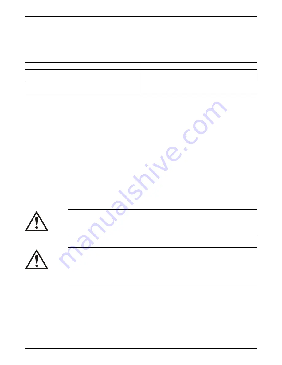
5.1.2  Priming

Type of installation

Procedure

Positive head on the suction

Open the suction and vent valve and allow the liquid to enter the

casing.

Suction lift

Use other methods such as foot valves, ejectors or by manually filling

the casing and suction line.

5.1.3  Starting

1. Close drain valves and valve in discharge line.
2. Open fully all valves in the suction line.
3. Prime the pump.

NOTE: If the pump does not prime properly, or loses prime during start-up, it should
be shut down and the condition corrected before the procedure is repeated.

4. When the pump is operating at full speed, open the discharge valve slowly. This

should be done after start-up to prevent damage to pump by operating at zero flow.

5.1.4  Operating checks

1. Check the pump and piping to assure that there are no leaks.
2. Check and record pressure gauge readings for future reference.
3. Check and record voltage, amperage per phase, and kw if an indicating wattmeter is

available.

4. Check bearings for lubrication and temperature. Normal temperature is 180°F

maximum.

5. Make all pump output adjustments with the discharge line.

CAUTION:

• Do not throttle the suction line to adjust the pump output.
• Do not let heated pump temperature rise above 150°F.

5.1.5  Check the rotation

WARNING:

• Operating the pump in reverse rotation can result in the contact of metal parts, heat

generation, and breach of containment.

• Always disconnect and lock out power to the driver before you perform any installation

or maintenance tasks. Failure to disconnect and lock out driver power will result in
serious physical injury.

1. Unlock power to the driver.
2. Make sure that everyone is clear, and then jog the driver long enough to determine

that the direction of rotation corresponds to the arrow on the pump.

3. Lock out power to the driver.

5  Commissioning, Startup, Operation, and Shutdown

24

G&L Pumps Series A-C 9100 Base Mounted Centrifugal Pumps INSTRUCTION MANUAL

Содержание G&L A-C 9100 Series

Страница 1: ...INSTRUCTION MANUAL AC5657C G L Pumps Series A C 9100 Base Mounted Centrifugal Pumps...

Страница 2: ......

Страница 3: ...undation requirements 14 4 1 4 Level the base on a concrete foundation 15 4 1 5 Grout the baseplate 15 4 2 Coupling alignment 16 4 2 1 Prepare for alignment 16 4 2 2 Align the pump using a straight ed...

Страница 4: ...ssembly inspections 34 6 7 1 Replacement guidelines 34 6 7 2 Shaft and sleeve inspection 34 6 8 Dimensions 35 6 9 Reassembly 35 6 9 1 Reassemble the pump with the mechanical seals on the shaft sleeve...

Страница 5: ...f parts not provided by Xylem If there is a question regarding the intended use of the equipment please contact a Xylem representative before proceeding Do not change the service application without t...

Страница 6: ...ls WARNING Do NOT exceed the maximum working pressure of the pump This information is listed on the nameplate of the pump Alert symbol This safety alert symbol is used in manuals and on the safety ins...

Страница 7: ...adable 1 3 User safety General safety rules These safety rules apply Always keep the work area clean Pay attention to the risks presented by gas and vapors in the work area Avoid all electrical danger...

Страница 8: ...ondition Action Chemicals or hazardous fluids in eyes 1 Hold your eyelids apart forcibly with your fingers 2 Rinse the eyes with eyewash or running water for at least 15 minutes 3 Seek medical attenti...

Страница 9: ...y will be packaged in a separate container and shipped with the pump or attached to the base plate Shaft alignment Shafts are in alignment when the unit is shipped however misalignment can occur due t...

Страница 10: ...tion to ensure the weight is balanced equally distributed across both forks When the baseplate of the assembly is structural channel construction the pump and base plate should be set in place first T...

Страница 11: ...ard shackle and end loops Be sure the lifting equipment is of sufficient length to keep the lift angle less than 30 from the vertical See Figure 3 Storage location The product must be stored in a cove...

Страница 12: ...or short term storage apply Store in a covered and dry location Store the unit free from excessive cold or heat below 32 F and above 110 F dirt and vibration Rotate the shaft by hand several times 10...

Страница 13: ...feed water Condensate Hydronic cooling or heating Pressure boosting General pumping Benign liquids 3 2 Operational specifications Maximum working pressure The maximum working pressure is listed on th...

Страница 14: ...for example 8 x 8 x 17M 4 Serial number for example 1 21937 1 1 5 Driver HP 6 Identification number for example Month and year CWP 11 7 Pump series and model number 8 Duty points GPM feet RPM 9 Maxim...

Страница 15: ...e Explanation comment Keep the pump as close to the liquid source as practically possible If the pump is not on a closed system locate the pump so that the fewest number of bends or elbows in the suct...

Страница 16: ...ast five times the weight of the pump unit Pour the foundation without interruption to within 1 2 to 1 1 2 inches of the finished height The top surface of the foundation should be scored and grooved...

Страница 17: ...1 for shims Place on both sides of anchor bolts 4 1 5 Grout the baseplate Required equipment Cleaners Do not use an oil based cleaner because the grout will not bond to it See the instructions provid...

Страница 18: ...with high speed rings hold both half elements on the hubs in order to make sure the hubs do not interfere with the rings 5 You can install the hubs with the hub extension facing in or out Make sure th...

Страница 19: ...in the 0 to 4 misalignment that is allowed for that size of coupling 1 2 1 Straight edge 2 Feeler guage Figure 4 Check the alignment using a straight edge correct 1 2 Angular Parallel 1 Straight edge...

Страница 20: ...gure 7 Pump alignment via dial indicator d Set the dial to zero e Rotate both coupling halves together and make sure that the index lines remain matched f Reposition the equipment until the offset is...

Страница 21: ...er 1 64 inch less then the diameter of the dowel pins 2 Ream the holes in feet and base to the proper diameter for the pins light push fit Clean out the chips 3 Insert pins to be approximately flush w...

Страница 22: ...selected and installed so that pressure losses are minimized and sufficient liquid flows into the pump when it is started and operated Many NPSH problems can be directly attributed to improper suctio...

Страница 23: ...ws the unbalanced loading of a double suction impeller due to the uneven flow around an elbow that is adjacent to the pump 1 2 3 4 5 1 Pump casing 2 Impeller 3 Pump suction flange 4 Suction elbow 5 Wa...

Страница 24: ...1 1 No air pockets 2 Eccentric reducer 3 Gradual rise Figure 14 Gradual rise to the pump correct 1 1 Distance plus eccentric reducer straightens the flow Figure 15 Suction pipe above the pump correct...

Страница 25: ...pipe system in order to prevent premature failure at initial startup If temperatures of the pumped fluid will exceed 200 F 93 C then warm up the pump prior to operation Circulate a small amount of fl...

Страница 26: ...rt up to prevent damage to pump by operating at zero flow 5 1 4 Operating checks 1 Check the pump and piping to assure that there are no leaks 2 Check and record pressure gauge readings for future ref...

Страница 27: ...r can only come off from the outboard end 2 With the rotating element out of the casing remove the casing from the bedplate and turn 180 3 Set the rotating element back in the casing and reassemble th...

Страница 28: ...Figure 18 Main joint bolts 5 Commissioning Startup Operation and Shutdown 26 G L Pumps Series A C 9100 Base Mounted Centrifugal Pumps INSTRUCTION MANUAL...

Страница 29: ...sary Use the grade recommended Make sure the seal cages are centered in the stuffing box at the entrance of the stuffing box piping connection Take vibration readings on the bearing housings Compare t...

Страница 30: ...d area it is unlikely that bearing replacement is necessary Only replace the bearings if rust or worn surfaces appear Inspect the stuffing box and clean out any foreign matter that will clog the box R...

Страница 31: ...down especially during the first 1000 hours CAUTION Do not over oil This causes the bearings to run hot Bearing lubrication schedule Type of bearing First lubrication assembled pumps and replacement b...

Страница 32: ...lubrication label on pump or bearing frame indicating polyurea base grease Pumps built before Dec 1 2014 were built with Lithium based greases NLGI 2 and do not have lubrication label on pump or beari...

Страница 33: ...ly before you install new packing Check the condition of the shaft or sleeve for possible scoring or eccentricity and make replacements as necessary When placing new non asbestos packing into the stuf...

Страница 34: ...drain plug located on the bottom of the pump housing Do not reinstall the plug or close the drain valve until the reassembly is complete 4 Drain the liquid from the piping and flush the pump if it is...

Страница 35: ...904 9 washers 1 909 9 and slide gland 3 014 2 away from casing 7 Remove all casing main joint capscrews 2 904 1 and dowels 2 916 9 Use slot in casing main joint and separate the casing halves with a p...

Страница 36: ...e parts Failure to do so may result in equipment damage 6 7 1 Replacement guidelines Impeller replacement This table shows the criteria for replacing the impeller Impeller parts When to replace Impell...

Страница 37: ...ing to determine the correct impeller rotation and locate the impeller on the shaft per dimension A given in table NOTE For impellers with replaceable rings heat each new ring 4 004 9 and slide it ont...

Страница 38: ...026 2 so that they will be ready when called for the next step Use dry heat from induction heat lamps or electric furnace or a 10 15 soluble oil and water solution IMPORTANT Do not exceed 275 F These...

Страница 39: ...ing housing Refer to NOTE under number 11 for direction of oil seal 16 Slide bearing housings 3 025 2 over bearings 3 026 2 17 Assemble bearing cover to bearing housing with two capscrews 3 904 9 18 R...

Страница 40: ...e deflectors 3 136 9 toward bearing covers Allow rotating clearance of approximately 1 16 26 Rotate shaft by hand to assure that it turns smoothly and is free from rubbing and binding 27 Bolt glands 3...

Страница 41: ...eal 3 177 9 in each bearing cover Install gaskets 3 409 9 on each bearing cover NOTE Seal lip or pressure side of oil seal must point towards the ends of the shaft that the oil seal is assembled on Se...

Страница 42: ...al in obtaining proper gasket compression so no leafage can occur at main joint CAUTION Double check rotation of pump before installing the upper half casing 23 Slide deflectors 3 136 9 toward bearing...

Страница 43: ...d shaft 6 Hold the guard in this position and tighten the three capscrews 7 Open the isolation valves and inspect the pump for leaks 8 Return the pump to service if it is not leaking 6 9 4 Adjustable...

Страница 44: ...the oil ring 1 Place the oil ring in the bearing housing directly under the pipe plug hole 2 Run a wire through the pipe plug hole around the oil ring and back through the pipe plug hole once again 3...

Страница 45: ...shed by inserting a phenolic disc or equivalent of a specified thickness between the motor and pump shaft 1 2 3 4 5 1 Cover 2 Phenolic disc 3 Pump shaft 4 Motor shaft 5 Hub Figure 26 Limited end float...

Страница 46: ...s unless specified as a material change All material substitutions should be discussed with the factory 6 9 8 2 Screw torque values Capscrew torque in ft lb Nm Capscrew type Head marking Capscrew diam...

Страница 47: ...atic lift may be too great Measure with mercury column or vacuum gauge while pump operates If static lift is too high liquid to be pumped must be raised or pump lowered Discharge head too high Check p...

Страница 48: ...d clean impeller Cavitation insufficient NPSH depending on installation 1 Increase positive suction head on pump by lowering pump 2 Sub cool suction piping at inlet to lower entering liquid temperatur...

Страница 49: ...let check for pipe friction losses Static lift may be too great Measure with mercury column or vacuum gauge while pump operates If static lift is too high liquid to be pumped must be raised or pump lo...

Страница 50: ...ection of rotor by turning on bearing journals Total indicator run out should not exceed 0 002 on shaft and 0 004 on impeller wearing surface Mechanical failure of critical pump parts Check bearings a...

Страница 51: ...8 Parts Listings and Cross Sectional Drawings 8 1 Parts list 8 Parts Listings and Cross Sectional Drawings G L Pumps Series A C 9100 Base Mounted Centrifugal Pumps INSTRUCTION MANUAL 49...

Страница 52: ...3 007 0 Shaft 1 1 3 009 9 Shaft sleeve 2 2 3 014 2 Gland mechanical seal 2 3 015 9 Shaft sleeve nut 2 2 3 018 3 Bearing housing cover inboard 1 1 3 018 4 Bearing housing cover outboard 1 1 3 025 2 bea...

Страница 53: ...9 O ring shaft sleeve 2 2 3 915 9 Snap ring 2 2 3 943 9 Spirol pin 2 2 4 002 0 Impeller 1 1 4 004 9 Impeller ring 2 optional 2 optional Recommended Spare parts 8 Parts Listings and Cross Sectional Dra...

Страница 54: ...arranted only for the balance of the warranty period on the parts that were repaired or replaced Seller shall have no warranty obligations to Buyer with respect to any product or parts of a product th...

Страница 55: ...repaired by third parties other than Seller or without Seller s written approval b subject to misuse misapplication neglect alteration accident or physical damage c used in a manner contrary to Seller...

Страница 56: ...e dealer from whom you purchased the product or visit www xyleminc com for the name and location of the nearest dealer providing warranty service 9 Product warranty 54 G L Pumps Series A C 9100 Base M...

Страница 57: ......

Страница 58: ......

Страница 59: ......

Страница 60: ...ng network technologies and advanced analytics solutions for water electric and gas utilities In more than 150 countries we have strong long standing relationships with customers who know us for our p...

Отзывы: