background image

1  Introduction and Safety

1.1  Introduction

Purpose of the manual

The purpose of this manual is to provide necessary information for installation,

operation, and maintenance of the unit.

Read and keep the manual

Save this manual for future reference, and keep it readily available at the

location of the unit.

CAUTION:

Read this manual carefully before installing and using the
product. Improper use of the product can cause personal injury
and damage to property, and may void the warranty.

The equipment, and its functioning, may be impaired if used in a manner not

specified by the manufacturer.

Intended use

WARNING:

Operating, installing, or maintaining the unit in any way that is
not covered in this manual could cause death, serious personal
injury, or damage to the equipment and the surroundings. This
includes any modification to the equipment or use of parts not
provided by Xylem. If there is a question regarding the
intended use of the equipment, please contact a Xylem
representative before proceeding.

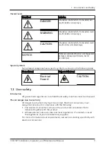
1.2  Safety terminology and symbols

About safety messages

It is extremely important that you read, understand, and follow the safety

messages and regulations carefully before handling the product. They are

published to help prevent these hazards:

• Personal accidents and health problems
• Damage to the product and its surroundings
• Product malfunction

1  Introduction and Safety

2

CCD 301 Installation, Operation, and Maintenance Manual

Содержание FLYGT CCD 301

Страница 1: ...Installation Operation and Maintenance Manual 885939_5 0 CCD 301...

Страница 2: ......

Страница 3: ...Purchaser to ensure adequate coverage in order for the modem to function properly at all times The modem is delivered with a built in SIM card Xylem has roaming agreements with selected operators depe...

Страница 4: ......

Страница 5: ...s 6 2 3 Extra parts 7 3 Installation 8 3 1 Connection and configuration Alarm management 8 3 1 1 Precautions 8 3 1 2 Requirements 9 3 1 3 Cables 9 3 2 Install the equipment to the unit 9 3 3 Check the...

Страница 6: ...ating installing or maintaining the unit in any way that is not covered in this manual could cause death serious personal injury or damage to the equipment and the surroundings This includes any modif...

Страница 7: ...Magnetic fields hazard Electrical Hazard CAUTION 1 3 User safety Introduction All government regulations local health and safety directives must be observed Prevent danger due to electricity All dang...

Страница 8: ...sibility for work done by untrained unauthorized personnel 1 4 End of life product disposal Handle and dispose of all waste in compliance with local laws and regulations EU only Correct disposal of th...

Страница 9: ...e substances can cause harm to human health or the environment To protect natural resources and to promote material re use please separate batteries from other types of waste and recycle them through...

Страница 10: ...2 Parts 2 3 1 4 5 6 7 8 WS008272A 9 Figure 1 CCD301 part number 803 49 00 Part Description 1 Antenna see Extra parts on page 7 2 LED red or green network signal strength 3 LED yellow connection to the...

Страница 11: ...ves to the unit 83 84 45 1 m cable with RJ45 connectors Connects a SRC 311 pump drive to the data cable splitter 83 84 46 3 m cable with RJ45 connectors Connects a SRC 311 pump drive to the data cable...

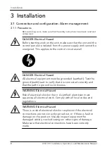
Страница 12: ...ground earth lead to verify that it is connected correctly and that the path to ground is continuous WARNING Electrical Hazard Risk of electrical shock or burn A certified electrician must supervise a...

Страница 13: ...ables must be in good condition not have any sharp bends and not be pinched The sheathing must not be damaged and must not have indentations or be embossed at the cable entry The minimum bending radiu...

Страница 14: ...ve to the terminals WS010556A RS 485 A B GND Signal lead color Unit terminal Brown A White or brown B White or green Ground earth Connect the two signals leads from the digital switch to the terminals...

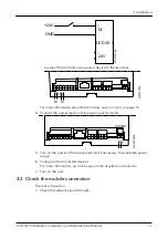
Страница 15: ...he power input terminals WS009630A 24 VDC 5 Turn on the power of the equipment and if necessary the separate power supply 6 Configure the connected devices For more information go to the support site...

Страница 16: ...ength is too low move the external antenna to another position 3 Check the connection to the cloud service LED State Connection WS010125A Blinks yellow every 5 s Yes Solid yellow No Unlit No The conne...

Страница 17: ...ground earth Make sure that the input voltage is more than 15 V The connection to the cloud service is slow Make sure that the equipment is not disconnected from the cloud service Repeated disconnect...

Страница 18: ...Operating humidity 95 relative humidity non condensing 5 3 Material UL94 V 0 Plastic materials 5 4 Approvals CE 5 5 Electrical data Feature Description Supply voltage 24 VDC Current Maximum 200 mA at...

Страница 19: ...C or not connected 2 Ground earth Analog input 3 4 20 mA 4 Ground earth Not used 5 Not used 6 Not used 7 Not used 8 Not used 2 Ethernet RJ45 3 RS 232 1 Rx RTU Tx 2 Tx RTU Rx 3 Ground earth 4 RS 485 wi...

Страница 20: ...metering network technologies and advanced analytics solutions for water electric and gas utilities In more than 150 countries we have strong long standing relationships with customers who know us for...

Отзывы: