


August 2020 – TD 316 OPERATING MANUAL – Motus Wave Sensor 5729
Page 27
2.3
Sensor offset compensation
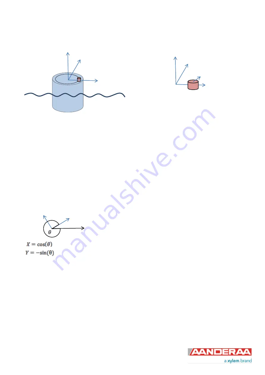
Figure 2-1: Buoy sensor offset geometry
The sensors axis system is defined by the orientation of the North mark of the sensor. This mark is aligned with the IMU
x-axis. The sensor offset installation on the buoy has to be described relative to the sensor axis system. The easiest
way to do this is to rotate the sensor such that the North mark on the buoy points directly away from the center of the
buoy. By doing this the sensor offset will be aligned with the sensor x-axis. In this case the radius offset will be the x-
axis offset, and the y-axis offset will be 0. The vertical offset is the height above the rotation origin. Normally the buoy
water line would be sufficient accurate as reference for the vertical component (Z) of the rotation origin.
In case the installation prevents the sensor x-axis orientation to be aligned with the installation offset vector, the offset
vector has to be decomposed into the sensor coordinate system according to
and
Figure 2-2: Offset vector decomposition
The IMU pitch and roll is used together with the installation offset of the sensor in order to calculate the additional
displacement of the sensor on a sample by sample basis and coherently subtract this value from the sensors reported
values. Sea trials in Norwegian fjords indicate that the error introduced when not compensating for this effect can be in
the order of 10 -15 % (40cm installation offset) depending on the sea state and spectral distribution of the waves.
Sensor-YN
Sensor-X(N)
Offset
X
Y
Z
X
N


