background image

en – Original Instructions 


18 

Installation, Operation and Maintenance Manual


4.3


Hydraulic connection 


WARNING: 

All the hydraulic connections  must be completed by a technician possessing the technical-

professional requirements outlined in the current regulations. 


WARNING: Excessive system pressure hazard 

Piping must be sized to ensure safety at the maximum operating pressure.  

The maximum pressure value  of the pump is listed on  the  data  plate.  Do  not  exceed  this 

pressure. 


WARNING: Excessive system pressure hazard 

The heating of water and other fluids causes volumetric expansion. The associated forces may 

cause failure of system components and the release of high temperature fluids. 

This can be prevented by installing properly sized and located compression tanks and pressure 

relief valves.  

4.3.1


Guidelines for the hydraulic system 

Recirculating pumps installed in the return line 


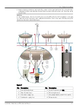
Before starting piping work shut off the water to the house and drain the affected sections of 

the plumbing lines and the water heater if necessary. 


Select the sink under which to connect the recirculation line (the sink where the hot water 

takes longest to arrive, which is usually the sink farthest from the water heater). 


Use 1/2" tubing for the recirculation line.  


Connect the return line with a tee fitting at the last faucet/taps riser, as close to the end of the 

hot water supply line as possible and run the line back to the water heater. 


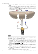
Decide on the course of the recirculation pipe (also determining the length of the pipe 

required) and whether the return line should be connected to the water heater cold water 

inlet line (tee fitting required) or  to the bottom water heater drain valve ("Y" type fitting 

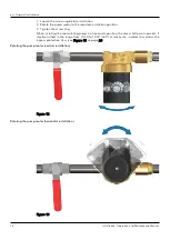
required to fit to existing drain valve outlet). See Figure 5 and Figure 6 on page 19 and 20 

for the installation schematic.  


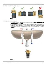
The pump must always be installed in the recirculation line, below the water level of the water 

heater.  


Do not mount the pump above the water heater, if possible, install the unit at the lowest point 

of the system.  


Do not install the unit pumping away from the water heater, or directly in the supply line. 


Support the pipes independently, so that their weight does not load the unit.  


Check to be sure there are no crimps or sharp bends in the recirculation line that would 

restrict the flow. 


Remove any welding residues, deposits and impurities in the pipes that could damage the 

unit. 


Check that other units do not come in contact with the unit. 


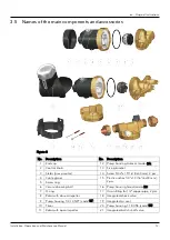
When using pump models with pump housing code BT or BS (item 9 and 16 in Figure 3 on 

page 13), use a 1/2" swing check valve with appropriate closing pressure. This prevents water 

from flowing through the pump backwards when any faucet is opened, thus causing damage.  


Install the check valve after the pump in the direction of flow, so that the arrows on the pump 

housing and on the check valve point in the same direction. 

Содержание 60A0B6001

Страница 1: ...Installation Operation and Maintenance Manual Series e3 4 e3 6 Instant hot water recirculating systems...

Страница 2: ...n 11 3 2 Integrated features and functions 11 3 3 Data plate 12 3 4 Model description 12 3 5 Names of the main components and accessories 13 3 6 Intended use 14 3 7 Improper use 16 4 Installation 17 4...

Страница 3: ...Maintenance 36 6 1 Precautions 36 6 2 Maintenance 36 6 3 Autocirc pumps 37 6 4 Disassembly 37 7 Troubleshooting 38 7 1 Precautions 38 7 2 Error signals 38 7 3 Pump not running 38 7 4 Pump running for...

Страница 4: ...documentation Special version pumps may be supplied with supplementary instruction manuals For situations not considered in the manual or in the sales document contact Xylem or the Authorized Distribu...

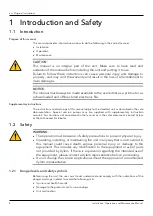
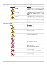
Страница 5: ...ntifies a dangerous situation which if not avoided may cause small or medium level injuries NOTICE It identifies a situation which if not avoided may cause damage to property but not to people Complem...

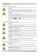
Страница 6: ...t according to NSF ANSI 61 SAFETY INSTRUCTIONS according to UL 778 CAUTION Acceptable for indoor use only This pump has been evaluated for use with water only Use with maximum 203 F 95 C water WARNING...

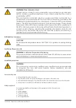
Страница 7: ...pump and have the problem corrected by a qualified service representative before using NSF ANSI 61 limitation CAUTION Do not allow the temperature above 140 F 60 C in systems circulating drinking wat...

Страница 8: ...components to cool before you handle them Make sure that the product has been thoroughly cleaned Disconnect and lock out power before you service the pump Precautions during work Observe these safety...

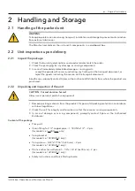
Страница 9: ...n on the transport document In both cases promptly contact Xylem or the Authorized Distributor from whom the product was purchased 2 2 2 Unpacking and inspection of the unit CAUTION Cut and abrasion h...

Страница 10: ...avoid injury to people and animals and or damage to property 2 4 Storage Storage of the packed unit The unit must be stored In a covered and dry place Away from heat sources Protected from dirt Protec...

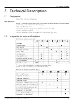
Страница 11: ...number 60A _ _0 60A _ _1 60A _ _2 60A _ _3 60A _ _4 60A _ _5 60A _ _6 Fix speed Variable speed PWM control Temperature control Timer control Standby mode Air purge function Error code flashing LED lig...

Страница 12: ...l min 6 6 gpm 23 l min 3 Motor control V Variable speed P PWM control only for OEM applications F Fix speed 4 Pump housing material B Brass D Plastic for drinking water NSF 61 compliant S Stainless s...

Страница 13: ...tor pump motor 14 Screw 5 32 x1 9 16 4x40 mm 2 pcs 4 Cable gland 15 Plastic anchor 1 4 x1 3 16 6x30 mm 2 pcs 5 Screw ring 6 Ceramic bearing ball 16 Pump housing Sweat code BS 7 O ring 17 Union fitting...

Страница 14: ...ated by the piping in the house water supply line and the return line NOTICE Water pressure A recirculating system is a pressurized system operating at the city water pressure as determined by the pre...

Страница 15: ...ep the hot water temperature below 140 F 60 C Higher temperatures can cause calcium and magnesium elements to come out of solution and create solids which could not only cause damage to the pump but a...

Страница 16: ...t is prohibited to use the unit to pump aggressive liquids acids and seawater DANGER Potentially explosive atmosphere hazard It is prohibited to start the unit in environments with potentially explosi...

Страница 17: ...e the pump and the piping is protected from freezing Install in one of the permitted mounting positions see Figure 8 on page 23 Observe the instructions given in the section 8 2 Operating environment...

Страница 18: ...he end of the hot water supply line as possible and run the line back to the water heater Decide on the course of the recirculation pipe also determining the length of the pipe required and whether th...

Страница 19: ...stall these components With the shut off valve closed at the suction side of the pump and with the check valve installed at the discharge side the screw ring item 5 in Figure 3 can be loosen thus the...

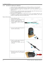
Страница 20: ...e unit is supplied with a 6 feet long grounded cord NOTICE The next installation guide applies to most situations where faucets taps are connected to the hot and cold water supply lines with braided f...

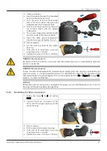
Страница 21: ...ICE In some older homes the riser shut off valves may be difficult to shut off completely or maybe it is necessary to turn the valves into a different orientation If this is the case shut the water of...

Страница 22: ...the shut off valve on the inlet side of the pump and turn the water supply to the house back on 8 Flush system of debris Before reattaching the pump motor open the shut off valve on the inlet side of...

Страница 23: ...the concerning instructions in section 4 3 1 Guidelines for the hydraulic system on page 20 21 2 Fasten the Autocirc unit to the wall under the sink using the wall bracket provided in the Autocirc ki...

Страница 24: ...replaced 5 Screw on the 9 16 end of the purchased flexible hoses to the outlet connections on the pump housing Screw on the 1 2 end of these same two hoses to the underside of the hot and cold water...

Страница 25: ...AUTION Be careful not to damage the internal seal risk of leakage of very hot or cold liquid during the operation of the unit CAUTION The use of PTFE impregnated pipe compound and PTFE tape on pipe th...

Страница 26: ...ion 3 Tighten the screw ring When installing the recirculating pump in a horizontal position the timer shall point upwards It may be turned in the range from 10 30 to 13 30 45 at maximum in order to m...

Страница 27: ...manner the GFCI is defective If the GFCI interrupts power to the pump without the test button being pushed a ground current is flowing indicating the possibility of an electric shock Do not use this...

Страница 28: ...e receptacle Do not use an extension cord If the pump unit is supplied without a power cord use only a UL certified SJTW type PVC insulated and sheathed hard service flexible cord with copper conducto...

Страница 29: ...all connections are secure and the conduit box cover is closed before electrical power is connected DANGER Electrical hazard Pumps that do not equipped with standard power supply plug may only be conn...

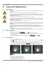
Страница 30: ...structions in section 4 Installation on page 17 have been performed The system has been flushed thoroughly to prevent foreign objects and impurities from blocking the pump The system has been filled a...

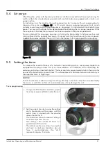
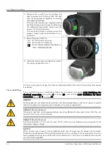
Страница 31: ...epeat the air purging Figure 15 5 5 Setting the timer To increase the overall efficiency of a hot water recirculating system some pump models are equipped with a plug in timer unit it is also availabl...

Страница 32: ...retrofitting If you install the timer as retrofitting follow the instructions of section 4 4 2 Guidelines for electrical connection only point 4 on page 28 and section 4 4 3 Guidelines for timer conn...

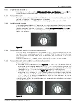
Страница 33: ...ith a control knob run on a constant speed if energized until reaching the factory preset temperature limit it is around 97 F 36 C as default then the pump stops and switches to standby mode When the...

Страница 34: ...as required during the programmed sequence of operation Do not be concerned if the pump does not begin running immediately after the pump is plugged in This just means that there is already hot water...

Страница 35: ...d models This algorithm protects the unit from dry running during normal operation This algorithm is a special version of the dry run protection If the expected power level cannot be restored in 3 x 9...

Страница 36: ...le working tools WARNING Hot water hazard Before draining the system allow water to cool to at least 100 F 38 C open the drain valve take precautions against water damage and leave the drain valve ope...

Страница 37: ...Disconnect the electrical supply lines to the pump Close the valves on the suction and discharge sides of the pump if no valves have been installed it may be necessary to drain the system Loosen the...

Страница 38: ...ion the pump is running Continuous on Air purge sequence is active Blinking 200 ms on 200 ms off 200 ms on Standby mode Blinking 50 ms on 1 5 s off 50 ms on Low voltage failure Blinking 1 x short 1 x...

Страница 39: ...line Add a check valve on the cold supply line above the return line tee connector If the noise occurs when an Autocirc pump turns off it is likely to be water hammer that results from the closure of...

Страница 40: ...tor NOTICE To avoid condensation in the stator or in the electronics the liquid temperature must be higher than the ambient temperature 8 3 Pumped liquid CAUTION This pump has been designed and tested...

Страница 41: ...Weight lb kg e3 _V BSPYZ 01 e3 _F BSPQZ 01 e3 _F BSPRZ 01 e3 _F BSPYZ 01 2 2 1 0 e3 _V BSXYZ 01 e3 _F BSXQZ 01 e3 _F BSXRZ 01 e3 _F BSXYZ 01 1 8 0 8 e3 _V BSPYC 01 e3 _F BSPQC 01 e3 _F BSPRC 01 e3 _F...

Страница 42: ...kg e3 _V BUPYZ 01 e3 _F BUPQZ 01 e3 _F BUPRZ 01 e3 _F BUPYZ 01 2 6 1 2 e3 _V BUXYZ 01 e3 _F BUXQZ 01 e3 _F BUXRZ 01 e3 _F BUXYZ 01 2 2 1 0 e3 _V BUPYC 01 e3 _F BUPQC 01 e3 _F BUPRC 01 e3 _F BUPYC 01...

Страница 43: ...en Original Instructions Installation Operation and Maintenance Manual 43 8 7 Hydraulic curves e3 4F BS__Z e3 4F BT__Z e3 4V BS__Z e3 4V BT__Z e3 4F BU__Z e3 4V BU__Z...

Страница 44: ...en Original Instructions 44 Installation Operation and Maintenance Manual e3 6F BS__Z e3 6F BT__Z e3 6V BS__Z e3 6V BT__Z e3 4F BAP_C e3 6V BU__Z...

Страница 45: ...Manufacturer applications the pump has customized versions which differ from the standard trade versions in some features An individual PSS Product Specification Sheet document is issued for each of t...

Страница 46: ...be disposed of through approved companies specialized in the identification of different types of materials steel copper plastic etc WARNING It is prohibited to dispose of lubricating fluids and other...

Страница 47: ...ty void Any parts repaired or replaced under the Warranty are warranted only for the balance of the warranty period on the parts that were repaired or replaced Seller shall have no warranty obligation...

Страница 48: ...s other than Seller or without Seller s written approval b subject to misuse misapplication neglect alteration accident or physical damage c used in a manner contrary to Seller s instructions for inst...

Страница 49: ...reating innovative solutions to meet our world s water needs Developing new technologies that will improve the way water is used conserved and re used in the future is central to our work We move trea...

Отзывы: