XVision XIR621 Скачать руководство пользователя страница 5

5

1.

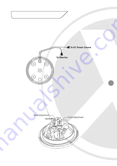
Connect the video output to the monitor or other video device 
through a 75 Ohms type coaxial cable.

2.

Connect the power source, insert the AC plug into the AC socket and 
the DC plug into the DC Jack (+12V DC in jack centre) (as shown in 

Figure 3).

3.

Once the picture appears on the monitor, open the cover and make

the Zoom Adjustment by rotating the screw (NEAR-Anti-clockwise,
FAR-Clockwise) until you get the desired view. Next make the Focal 

Adjustment by rotating the screw (TELE-Anti-clockwise, WIDE-

Clockwise) until you get the desired view (as shown in Figure 4).

4.

Tighten the two screws, then replace the dome cover.

6. How to Operate

Figure 3

Figure 4

Содержание XIR621

Страница 1: ...ed by the warranty The camera is suitable for indoor or outdoor use Please bear in mind the following points when choosing a mounting position The camera must be positioned so that it will not point directly into the sun sunrise and sunset or any bright light as this may cause damage to the camera Avoid viewing areas where half the area is in bright sunlight and the other half is dark such as in t...

Страница 2: ...If you need to clean the cover use cotton wool balls dipped in alcohol or glass wipes The XIR621 colour vandal resistant nightvision dome camera is designed for high risk applications It offers very high resolution 550 TVL images from its Sony 1 3 Ex View CCD sensor and will provide images in complete darkness up to 25 metres and beyond 25 metres in light levels above 0 05 lux It features an Auto ...

Страница 3: ...ion Dynamic Night View technology provides clear images without the need for IR LEDs down to 0 002 lux this is achieved by using Field Integration please note due to way in which field integration works whilst it is in operation the frame per second will reduce The darker the scene the lower the frame per second Smart DNR Digital Noise Reduction reduces the noise on the image when viewing in low l...

Страница 4: ... fixing screws as shown in Figure 1 Figure 1 5 Installation 4 Adjust the camera viewing angle by first tilting STEP 1 then rotating the camera module STEP 2 and then turn the horizontal adjustment ring STEP 3 to correct the image and achieve proper orientation as shown in Figure 2 5 Place the dome cover on the camera and tighten it by turning it clockwise Camera Module Horizontal Adjustment Ring T...

Страница 5: ...e as shown in Figure 3 3 Once the picture appears on the monitor open the cover and make the Zoom Adjustment by rotating the screw NEAR Anti clockwise FAR Clockwise until you get the desired view Next make the Focal Adjustment by rotating the screw TELE Anti clockwise WIDE Clockwise until you get the desired view as shown in Figure 4 4 Tighten the two screws then replace the dome cover 6 How to Op...

Страница 6: ...ra OSD Control 8 OSD Menu Structure Push DOWN to Setup menu LENS DC MANUAL AUTO OFF SHUTTER OFF FLK MANUAL ESC WHITE BAL ATW AWC MANUAL BACKLIGHT OFF LOW MIDDLE HIGH AGC OFF LOW MIDDLE HIGH OFF LOW MIDDLE HIGH DNR CAMERA ID COLOUR SYNC MOTION DET PRIVACY MIRROR SHARPNESS RESET RETURN SPECIAL SENS UP DSS EXIT SET UP MENU ...

Страница 7: ... adjust the shutter speed from 1 60 1 120 000 of a second NTSC or 1 50 1 100 000 PAL FLK is the only option available when the camera lens is set to the recommended DC mode 3 COLOUR Option AUTO ON AUTO Automatically detect colour or black white ON Full time colour mode 4 SYNC Option INT L L INT Synchronize the vertical interval sync pulse of your camera with other equipment to reduce the effect of...

Страница 8: ... MOTION DETECTED along with the number of movements counted Select the area on screen you want to observe AREA SEL Select a motion detection grid top left top right bottom left bottom right to modify AREA STATE Activate or deactivate the selected grid TOP DOWN LEFT RIGHT Press LEFT or RIGHT menu control left or right to alter the dimensions of the selected grid 6 PRIVACY Option OFF ON Mask up to 4...

Страница 9: ...d grid TOP DOWN LEFT RIGHT Press LEFT or RIGHT menu control left or right to alter the dimensions of the selected grid 7 MIRROR Option OFF ON Adjust level of sharpness contrast CB_Gain CR_Gain 8 SHARPNESS Option OFF ON Sharpen the image on screen Excessive sharpening may cause picture noise 9 RESET Restore all factory default settings 10 RETURN Return to the main SETUP menu ...

Страница 10: ... title UP DOWN LEFT RIGHT menu control Select a character then press SETUP MENU to accept it The character is saved and the title cursor at the bottom of the screen moves to the next position Go back or forward in the title name to make changes CLR Delete the entire name and start again POS Position the camera title on the screen Press SETUP MENU to confirm the position END Accept the new name 10 ...

Страница 11: ...n X3 DSP Software Samsung DSP Chip Resolution 550 TVL Lens Viewing Angle 26 to 92 Infra Red Nightvision 25 metres Minimum Illumination 0 Lux IR On 0 002 Lux Audio No Operating Voltage 12V DC 450mA Suggested Power Supply 12V DC 1250mA Regulated Mounting Wall Ceiling Weatherproofing Yes Dimensions ØxD 132mm x 115mm ...

Страница 12: ...ur local distributor LIMITED WARRANTY This product is supplied with a limited 3 Year warranty The Warranty excludes products that have been misused including accidental damage and damage caused by normal wear and tear In the unlikely event that you encounter a problem with this product it should be returned to the place of purchase Should you require replacement LEDs please contact your local dist...

Отзывы: