


Operation Manual
45
Operation Manual
Operator Cab
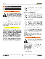
Boom Angle Indicator
The boom angle indicator is located on the left side of the
boom and is visible from the operator’s seat. Use the boom
angle indicator to determine the boom angle when referring
to load capacity charts. Refer to the LOAD CAPACITY CHARTS
section of this manual for more information.
NOTE: The boom angle indicator is a plumb arrow with angu-
lar graduations from -50 to +700
Figure 54. Boom Angle Indicator
Boom Extend Letters
As the boom is extended, the boom extend letters on the left
side of the boom are visible to the operator. These letters
indicate boom extension as it corresponds to the load capacity
charts.
Figure 55. Boom Extend Letters
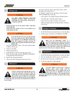
Frame Level Indicator
The frame level indicator is mounted on the upper right
corner of the operator’s cab. The frame level indicator allows
the operator to view if the Telehandler has been positioned in
a level condition.
Figure 56. Frame Level Indicator
Figure 57. XR1555 Lifting Points
Telehandler Lifting Points
The XR1555 lifting points are shown below. The Telehandler
should only be lifted if lifting points are installed.
Warning
Ensure that no one is in the work radius
before lifting Telehandler to avoid crushing
hazard.
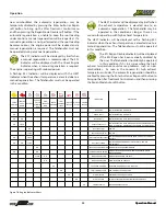
MODEL: XR1255
UNLADEN VEHICLE WEIGHT: 36,100 lbs
18241-001
UNLADEN CENTER OF GRAVITY
AFT LIFT POINT
FORWARD LIFT POINT
141.0"
WHEEL BASE
77.0"
APPROX


