Xtreme Power Conversion Corporation
TX90 6kVA & 10kVA Service Manual
Page 31
Uninterruptible Power Supply
• Fill the output voltage measured by the power meter to Calibration Step2, then click ”Calibration2” icon.
• Press Calibration 2 icon after the figure is filled, then buzzer will beep twice to show the calibration is
complete.
• After calibration, the output voltage will be changed and remained for approx. 4 seconds. Please quickly
check with Power meter if the output voltage shown as below:
• The output voltage shall be 220.7 +/-0.3V (220.4V~221.0V) if no transformer is installed.
• Otherwise, please refer to the followings if there is a transformer installed.
Setting calibration parameter
Output Voltage Range
I/P
→
Else system, O/P
→
240V system
225.0 +/-0.3V (224.7V~225.3V)
I/P
→
Else system, O/P
→
120V system
112.5 +/-0.3V (112.2V~112.8V)
I/P
→
208V system, O/P
→
208V system
225.0 +/-0.3V (224.7V~225.3V)
I/P
→
208V system, O/P
→
120V system
129.8 +/-0.3V (129.5V~131.1V)
Caution:
• You are suggested to connect with 80% to 100% load in order to make sure the tolerance of the calibrated
values will be smaller and the values will be more accurate. All values will be calibrated except the value
of load% if the output load of UPS are less than 30% when you proceed calibrated action.
• Make sure the tolerance of the adjustable range will be less than 8% for Voltage and 15% for Load; other-
wise, the setting will be in failure and the error code will be shown in the LCD panel.
• The UPS will escape from calibration mode if the setting is not complete in 10 min. after the UPS is in the
calibration mode.
• The values of both “load%” and “output voltage” must be round to Integer.
• The input voltage in the Calibration 2 shall be accurate; therefore, make sure you will round the value
to 1st decimal place.
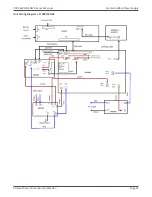
The Wiring Diagram of the Transformer (The red lines indicated below are for the connections of the no load in
calibration.)


