background image

Xtreme Power Conversion Corporation

P90g User’s Manual

Page 29

Uninterruptible Power Supply

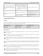
Fault Reference Codes

Fault event

Fault code

Icon

Fault event

Fault code

Icon

Bus start failure

01

X

Inverter output short

14

Bus over

02

X

Battery voltage too high

27

X

Bus under

03

X

Battery voltage too low

28

Bus unbalanced

04

X

Over temperature

41

X

Inverter soft start fail

11

X

Overload

43

High inverter voltage

12

X

Low inverter voltage

13

X

Warning Indicators

Warning

Icon (flashing)

Code

Alarm

Low battery

Sounds every second

Overload

Sounds twice every second

Battery not connected

Sounds every second

Overcharge

Sounds every second

Site wiring fault

Sounds every second

EPO enable

Sounds every second

Over temperature

Sounds every second

Charger failure

Sounds every second

Battery fault

Sounds every second

Bypass out of range

Sounds every second

Bypass frequency unstable

Sounds every second

Содержание P90g Series

Страница 1: ...P90g Online UPS 1500VA 3000VA Models User Installation Manual www xpcc com 2016 Xtreme Power Conversion Corporation All rights reserved Rev 5 03 16 ...

Страница 2: ...ions 10 Hardware Installation Guide 11 UPS Installation 12 Starting the UPS 17 SoftwareInstallation 17 Battery Replacement 18 Operations 20 ButtonOperation 20 LCDPanel 21 Audible Alarms 22 Abbreviations in LCD Display 22 UPS Setting 23 Operating Mode Description 27 Fault Reference Codes 29 Warning Indicators 29 Troubleshooting 30 Storage Maintenance 31 Storage 31 Maintenance 31 Batteries 32 Specif...

Страница 3: ... Xtreme Power Conversion Limited Warranty 36 Xtreme Power Conversion Load Protection Policy 37 Appendix A P90 BP36 P90 BP72 User Guide 40 Important Safety Instructions 40 Product Overview and Setup 40 Type of Battery Required 42 Battery Replacement 42 WiringDiagram 47 Storage Maintenance 49 ...

Страница 4: ...or mation that should be followed during installation and maintenance of the UPS and batteries allowing you to cor rectly set up your system for the maximum safety and performance Included is information on customer support and service if it is required If you experience a problem with the UPS please refer to the Troubleshooting section in this manual to correct the problem If the problem is not c...

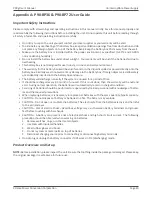
Страница 5: ... dispose of batteries in a fire the battery may explode CAUTION Do not open or mutilate the battery released electrolyte is harmful to the skin and eyes CAUTION A battery can present a risk of electric shock and high short circuit current The following precaution should be observed when working on batteries Remove watches rings or other metal objects Use tools with insulated handles To reduce the ...

Страница 6: ...ce personnel Before conducting any maintenance repair or shipment first ensure that everything is turned off com pletely and disconnected For additional safety instructions please use the Safety Manual as a reference Special Symbols The following symbols used on the UPS warn you of precautions RISK OF ELECTRIC SHOCK Please observe the warning that a risk of electric shock is present CAUTION REFER ...

Страница 7: ...wer company ac cidents and radio transmission motors air conditioners and vending machines Protection of sensitive electrical equipment is vital to protect against power outages low or high voltage conditions slow voltage fluctuations frequency variations differential and common mode noise transients etc To prevent power line problems from reaching critical systems causing damage to software hardw...

Страница 8: ... taken into consideration The total demand of the protected system shall dictate the output power rating VA Allow a margin for future expansion or calculation inaccuracies from measured power requirements Backup time required will indicate the battery size needed If the load is less than the UPS nominal power rating then actual backup time is longer The following options are available o Connectivi...

Страница 9: ...Xtreme Power Conversion Corporation P90g User s Manual Page 9 Uninterruptible Power Supply Front Panel Selector buttons Rack Display Tower Display ...

Страница 10: ... Communications Option The UPS provides an intelligent slot for internal or external network card This special intelligent network card can be compatible with popular software and hardware found on the web and in operating systems It can support op erating systems such as HP Open View IBM Netview SUN Netmanager etc This enables the UPS to provide instant UPS and power information over the network ...

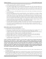
Страница 11: ... may exist in which no electrical equipment should be operated The instructions in this manual explain how to install the UPS safely Not acknowledging such electrical hazards may be fatal keep this manual for future reference WARNING It is strongly recommended that the UPS cabinet not be opened as components have very high voltage and touching those components may be fatal Only a qualified technic...

Страница 12: ...ordance with the local electrical laws and regulations and per formed by appropriate personnel For safety considerations the UPS is shipped from the factory with battery wire disconnected Before installing the UPS please follow these steps to connect of the battery wires Connecting the batteries Step 1 Step 2 Remove the front panel Connect the battery wires ...

Страница 13: ...t corners of the UPS Slide the UPS into the rack and secure using hardware provided Step 3 Rack mount Installation using front brackets Step 1 Step 2 Rack mount Installation using 4 post rail kit Package contents Right and left rail sliders 1 each 2 M6 nuts 12 M6 screws Place the front cover back on the front of the UPS ...

Страница 14: ...rsion Corporation P90g User s Manual Page 14 Uninterruptible Power Supply Step 1 Use 4 screws to mount right and left rail sliders in front of rack Step 2 Use 4 screws to mount right and left rail sliders in back of rack ...

Страница 15: ...on P90g User s Manual Page 15 Uninterruptible Power Supply Step 3 Place the nuts in the proper location in the rack based upon height of UPS Step 4 Carefully place the UPS on the rail support Step 5 Fix the UPS in position with screws ...

Страница 16: ...r s Manual Page 16 Uninterruptible Power Supply Inter connect the tower brackets that shipped in the box with the UPS Carefully lower the UPS into the brackets as shown Step 6 Rail kit installation is now complete Tower Installation Step 1 Step 2 ...

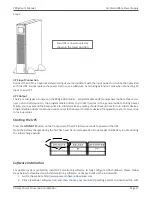
Страница 17: ...rter backup time for non critical devices Programmable outlets can also be used to re cycle the power to remote devices if required to re start a server due to lock up issues Starting the UPS Press the ON MUTE button on the front panel of the UPS for two seconds to power on the UPS Note the battery charges during the first five hours of normal operation Do not expect full battery run time during t...

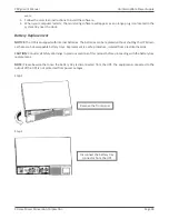
Страница 18: ... batteries The batteries can be replaced without shutting the UPS down as these are hot swappable battery trays Replacement is a safe procedure isolated from electrical hazards CAUTION Consider all Safety Warnings in previous sections of this manual before proceeding with the battery tray replacement NOTE Please beware that once the battery tray is disconnected from the UPS the equipment connected...

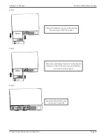
Страница 19: ...ible Power Supply Pull out the battery tray by removing the two screws on the front panel Step 3 Step 4 Step 5 Slide the new battery tray back to the original location in the UPS and secure with the two screws to the front panel Reconnect the battery tray connector to the UPS ...

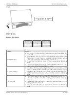
Страница 20: ...witch to UPS self test mode Press and hold ON MUTE button for 5 sec onds to enter UPS self testing while in AC mode OFF ENTER Button Turn off the UPS Press and hold the button more than 2 seconds to turn off the UPS The UPS will be in standby mode under normal power or transfer to bypass mode if the Bypass enable setting is set by pressing this button Confirm selection key Press this button to con...

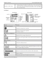
Страница 21: ...tes the backup time in pie chart Indicates the backup time in numbers H hours M minutes Warning Fault information Indicates that the warning and fault occurs Indicates the warning fault codes and the codes are listed in details in this manual Setting Operation Indicates the setting operation Input Output Battery information Indicates the output input voltage output input frequency or battery volt ...

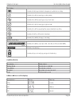
Страница 22: ...he output directly from utility Indicates that the UPS alarm is disabled Indicates the battery charger is working Battery information Indicates the Battery level by 0 25 26 50 51 75 and 76 100 Indicates low battery Indicates there is something wrong with the battery Audible Alarms Description Buzzer status Battery Mode Sounds every 4 seconds Low Battery Sounds every second Overload Sounding twice ...

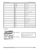
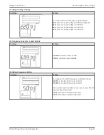
Страница 23: ...tery is not connected O C Overcharge S F Site Fault E P EPO T P Over Temperature C H Charger Failure B B Battery Fault F U Frequency Unstable in Bypass Mode B V Input Voltage is Out of Bypass Range UPS Setting There are two parameters to set up the UPS Parameter 1 for program alternatives there are 9 programs to set up Parameter 2 for setting information display ...

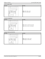
Страница 24: ...oltage as 230VAC 240 presents output voltage as 240VAC 02 Frequency Converter enable disable Interface Setting CF ENA converter mode enable CF DIS converter mode disable 03 Output Frequency Setting Interface Setting You may set the initial frequency on battery mode BAT 50 sets output frequency to 50Hz BAT 60 sets output frequency to 60Hz If converter mode is enabled you may choose the fol lowing o...

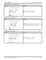
Страница 25: ...r Supply 04 ECO enable disable Interface Setting ENA ECO mode enable DIS ECO mode disable 05 AECO enable disable Interface Setting ENA Advanced ECO mode enable DIS Advanced ECO mode disable 06 Bypass Mode enable disable Interface Setting ENA Bypass mode enable DIS Bypass mode disable ...

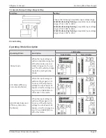
Страница 26: ...e outlets enable DIS Programmable outlets disable 08 Programmable Outlets Setting Interface Setting 0 999 setting the backup time limits in minutes from 0 999 for programmable outlets connected to non crit ical devices when operating in battery mode 09 LCD Display Direction Setting Interface Setting RAC the LCD display is horizontal TOE the LCD display is vertical ...

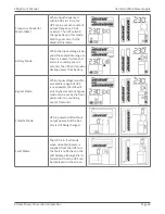
Страница 27: ...perating Mode Description LCD Display Rack Display Tower Display Online Mode When the input voltage is within acceptable range the UPS will provide pure and stable AC power to the out put The UPS will also charge the battery during Online Mode ECO Mode Efficiency Corrective Optimizer When the input voltage is within setting range 3 Vo max UPS will provide voltage to output via static bypass circui...

Страница 28: ... or there is a power failure and alarm is sounding every 4 seconds the UPS will provide backup power from battery Bypass Mode When input voltage is within acceptable range but UPS is overloaded the UPS will enter bypass mode or bypass mode can be set by the front panel Alarm is sounding every 10 seconds Standby Mode UPS is powered off without output power but the bat tery is still being charged Fa...

Страница 29: ...Inverter soft start fail 11 X Overload 43 High inverter voltage 12 X Low inverter voltage 13 X Warning Indicators Warning Icon flashing Code Alarm Low battery Sounds every second Overload Sounds twice every second Battery not connected Sounds every second Overcharge Sounds every second Site wiring fault Sounds every second EPO enable Sounds every second Over temperature Sounds every second Charger...
Страница 30: ...splay and alarm is continuously sound ing Battery voltage is too high or the charger is in fault condition Contactyour dealer for support Fault code is shown as 28 and the icon is showing on LCD display and alarm is continuously sound ing Battery voltage is too low or the charger is in fault condition Contactyour dealer for support The icon and are flashing on LCD display and alarm is sounding twi...

Страница 31: ...enance The UPS system operates with hazardous voltages Repairs may be carried out only by qualified mainte nance personnel Even after the unit is disconnected from the mains components inside the UPS system are still connected to the battery packs which are potentially dangerous Before carrying out any kind of service and or maintenance disconnect the batteries and verify that no current is presen...

Страница 32: ... local regulation Do not open or destroy batteries Escaping electrolyte can cause injury to the skin and eyes It may be toxic Please replace the fuse only with the same type and amperage in order to avoid fire hazards Do not disassemble the UPS system The UPS contains no user serviceable parts Batteries The life of batteries used in these UPS products is estimated at 3 6 years depending on level o...

Страница 33: ...1 7 lbs 65 7 lbs Line cord 8 ft C13 to L6 20P 8 ft C19 to L6 20P Receptacles 8 IEC C13 1 IEC C19 6 IEC C13 OPTIONAL Model number P90 BP36 36E P90 BP72 BATTERY PACKS Dimensions W x D x H 17 2 x 19 9 x 3 5 in 17 2 x 24 8 x 3 5 in E 17 2 x 24 6 x 3 5 in Weight 58 1 lbs 104 4 lbs E 104 4 lbs Battery 6 12V 9AH 36V 12 12V 9AH 36V E 12 12V 9AH 72V ENVIRONMENT Operating temperature 32 104 F 0 40 C Audible...

Страница 34: ...er Conversion Corporation P90g User s Manual Page 34 Uninterruptible Power Supply Shipping List 1 ViewPower CD 2 horizontal brackets front 3 tower stand brackets 4 manual 5 4ft USB cable 6 8ft L6 20P input cable ...

Страница 35: ...ask you for the above information and if possible help solve your problem over the phone In the event that the unit requires factory service the technician will issue you a Return Mate rial Authorization number RMA If you are returning the UPS to Xtreme Power for service please follow these procedures 1 Pack the UPS in its original packaging If the original packaging is no longer available ask the...

Страница 36: ...quipment is repaired or modified by anyone other than XPC Corporation or a XPC Corporation approved third party b the equipment is damaged by the customer is improperly used or stored is subjected to an adverse operating environment or is operated outside the limits of its electrical specifi cations or c the equipment has been used or stored in a manner contrary to the equipment s operating manual...

Страница 37: ...PC Limited Warranty against certain losses caused by a Power Disturbance for properly connected electronic equipment referred to as the Connected Equipment subject to certain terms and conditions provided below This policy applies only to the original purchaser of the Product If the Product is transferred or sold to another person or entity this policy is void Load Protection Policy Dollar and Per...

Страница 38: ...ad Protection Policy The following damage is not covered by this Policy 1 Restoration of lost data and reinstallation of software 2 Damage from a cause other than AC power line transients except for damage due to telephone line Local Area Network or CATV transients which is covered only if the Product offers such protection 3 DAMAGE CAUSED BY FAILURE TO PROVIDE A SUITABLE INSTALLATION ENVIRONMENT ...

Страница 39: ...e payment to the Purchaser for either the cost of repair of the Connected Equipment or the Fair Market Value of the damaged Connected Equipment up to the dollar limits stated above XPC reserves the right to require the Purchaser to transfer title and deliver the Connected Equipment to XPC if it chooses to reimburse the Purchaser for the fair market value of the Connected Equipment XPCs maximum lia...

Страница 40: ...box enclosure The battery will discharge naturally if the system is unused for a period of time It should be recharged every 2 3 months if unused If this is not done then the warranty will be null and void During normal operation the batteries will automatically remain in charged condition Servicing of batteries should be performed or supervised by trained personnel with knowledge of batter ies an...

Страница 41: ...is necessary to select a proper environment to install the unit in order to minimize the possibility of damage to the battery box and extend the life of the batteries Please follow the instructions below 1 Keep at least 20cm 8 inches clearance from the rear panel of the unit from the wall or other obstructions 2 Do not block the air flow to the ventilation openings of the unit 3 Please ensure the ...

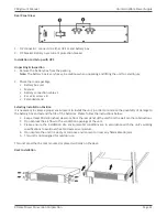
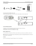
Страница 42: ...gned to operate with the following types of batteries 36V 9Ah Version 3 pieces of 12V 9Ah batteries per string 72V 9Ah Version 6 pieces of 12V 9Ah batteries per string Battery Replacement If your battery box is not installed with batteries please follow proper procedure to put batteries inside of unit NOTE MAKE SURE THAT THE BATTERY BOX IS DISCONNECTED FROM THE UPS BEFORE PERFORMING THE FOLLOW ING...

Страница 43: ...t panel part by pulling it from the lower extremity Step 3 Remove the fixed part of the front panel by removing the 2 screw present Step 4 Remove the metal top cover of the battery box by unscrewing 6 screws present on the two sides 3 on the right side and 3 on the left side 3 screws on the top and 4 screws on the back side ...

Страница 44: ...To install the second string of batteries repeat the same procedure on the battery hold down brackets on the right side of the battery box Step 6 Now it is possible to put all batteries inside the unit by following the below picture the following drawing are indicates the wire fastener positions for the correct battery placement Note To install the second string of batteries repeat the same proced...

Страница 45: ...plate and the two parts of the front panel and secure it with screws Step 10 Connect the battery box to the UPS P90 BP72 Step 1 Open the package and place the battery box on a horizontal plane Step 2 Remove the removable front panel part by pulling it from the lower extremity Step 3 Remove the fixed part of the front panel by removing 2 screw present Step 4 Remove the metal top cover of the batter...

Страница 46: ... second branch of batteries repeat the same procedure on the battery fixing plate on the right side of battery box Step 6 Now it is possible to put the batteries inside following below picture in the following drawing are indicated the fasten positions for the correct batteries placing Note To install the second string of batteries repeat the same procedure on the right side of battery box Step 7 ...

Страница 47: ...the second string of batteries repeat the same procedure on the right side of battery box Step 9 Put the metal top cover back on the unit Close the front fixing plate and the two parts of the front panel and secure it with screws Step 10 Connect the battery box to the UPS Wiring Diagram P90 BP36 Batt Link PCBA Batt Link PCBA Breaker 1st battery bench 2nd battery bench RED BLACK RED BLACK ...

Страница 48: ...M M 350M M 450M M 150M M 150M M Note The cable connection from the external battery connector to PCB is already present inside the battery box All the other cable connections should be made in accordance with the above wiring diagram P90 BP72 BattLinkPCBA BattLinkPCBA Breaker 1stbatterybench 2nd batterybench RED RED BLACK BLACK ...

Страница 49: ...ble parts If the battery service life 3 5 years at 25 C ambient temperature has been exceeded the batteries must be replaced In this case please contact your dealer Be sure to deliver the spent battery to a recycling facility or ship it to your dealer in the replacement battery packing material Storage Before storing charge the unit 4 hours Store the unit covered and upright in a cool dry location...

Отзывы: