background image

Ducts Application Note 


VESDA-E 

35424_02 


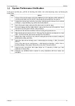
VESDA-E System Commissioning 


Hole Orientation Adjustment 

3.1.1  VESDA-E VEP-1P 

The differential pressure across the inlet and exhaust pipes must be kept within ±20 Pa to ensure the normal 
operation of the smoke detector. Differential pressure is created by the orientation of the holes on both pipes 
in relation to the duct flow. There are three methods for adjusting hole orientation. Your choice of method will 
depend on what equipment is available to you. 

1. 

Method 1 takes about 5 to 15 minutes, not including air flow normalization. No special equipment 
required. 

Step 

Action 

Ensure that the ventilation duct system is operating and airflow is present in the duct. 

Drill holes in the inlet and exhaust smoke detector pipes as required. 

Connect the inlet and exhaust pipes to the detector while the pipes are outside the duct. 

Normalize the airflow to the smoke detector and then record the %Flow. 

Insert the inlet and exhaust smoke detector pipes in the duct with the holes facing the 
airflow and record %Flow at the smoke detector. 

Slightly rotate the pipes so that the %Flow is within 5% of the original reading. 

Mark the position of the pipes’ orientation on the duct and pipes. This will make re-
positioning the pipes easy after maintenance checks in the future. 

Secure the pipe installation. 


2. 

Method 2 requires no connection to the smoke detector. Inlet and exhaust pipes are installed inside the 
duct. A manometer, for instance, Model 8702 DP-CALC Micromanometers from 

www.tsi.com

 will be 

required. 

Step 

Action 

Connect the ends of the inlet and exhaust smoke detector pipes to a pressure manometer 
as shown (Figure 8), ensuring that all connections are airtight. 

Face the holes of both pipes to the airflow and slightly rotate the pipes so that the pressure 
reading is within ±20 Pa. 

Mark the position of the pipes’ orientation on the duct and pipes. This will make re-
positioning the pipes easy after maintenance checks in the future. 

Connect the detector after securing the pipe network. 

Содержание VEA-040-A00

Страница 1: ...DUCTS APPLICATION NOTE February 2021 Doc No 35424_02 ...

Страница 2: ...rmation contained in this document will assist you when designing VESDA E systems for this type of application Note This system is not suitable for use in flexible ducts Related Products VESDA E VEP 1P and VEA detectors have been specially adapted for installation in ducts Their model numbers are VEP A00 1P VEA 040 A00 and VEA 040 A10 Copyright 2021 Xtralis AG ...

Страница 3: ...5 1 3 2 VESDA E VEA 5 2 VESDA E System Installation 6 Environmental Conditions 6 2 1 1 VESDA E VEP 1P 6 2 1 2 VESDA E VEA 7 Key Installation Considerations 7 3 VESDA E System Commissioning 8 Hole Orientation Adjustment 8 3 1 1 VESDA E VEP 1P 8 System Performance Verification 10 4 System Maintenance 11 Local Codes Standards 11 First Year Requirements 11 On Board Filter Replacement 11 Site Visit Req...

Страница 4: ...t a quarter of the height of the duct Figure 1 Side view of the inlet and exhaust pipe positions for a small ventilation duct A top view of the above installation is shown below Figure 2 The number of inlet pipe sampling holes their required size and spacing are listed in Table 1 Both sampling pipe and exhaust pipe holes have the same orientation with respect to the direction of the duct airflow F...

Страница 5: ...2 m 0 66 ft 1 1 2 VESDA E VEA Return air sampling is achieved with microbore tubes for VEA system inserted in the return air duct behind the exhaust grill it is recommended the tubes are installed facing perpendicular to the duct airflow Figure 3 A specific sampling point VSP 980 ST No 35295 must be used for VEA s duct sampling It can be mounted on the duct by VEA Sampling Point Duct Bracket part ...

Страница 6: ...ecommended that the inlet pipe of the smoke detector be in two branches The figure below Figure 5 shows a side view of a duct section with the relative insertion points for the inlet and exhaust pipes The two inlet branches are located at a quarter of the height H of the duct with the exhaust pipe inserted mid height approximately 0 5 m 1 64 ft downstream of the inlet pipes Figure 5 Side view of t...

Страница 7: ...ole spacing is 0 4 m 1 3 ft The exhaust pipe must have 4 Ø10 mm 13 32 inch sampling holes regardless of the width of the duct These holes should be located in the middle of the duct width at least 50 mm 2 inches from the side walls Note Calculations performed with the ASPIRE pipe design software tool and shown in Tables 1 and 2 apply to a 5 m 16 4 ft inlet pipe and a 2 m 6 56 ft exhaust pipe These...

Страница 8: ...duct is poor it is recommended that all holes on the inlet and exhaust pipes face downstream that is 180 to the incoming airflow The pipes should always be held in position at the duct walls with fittings such as rubber grommets Silicon is recommended to ensure an airtight seal Regardless of duct width the exhaust pipe must have 4 Ø10 mm 13 32 inches holes Never simultaneously sample from multiple...

Страница 9: ...utside the duct where the detector is to be installed and the temperature of the air inside the sampling pipes of the detector You should measure the temperature and humidity both inside the duct and in the area where the detector will be installed If the results indicate that condensation may be a problem refer to the Duct Sampling and Condensation section of the Pipe Network Installation Manual ...

Страница 10: ...tream of humidifiers heating coils and filters Upstream of fresh air intakes For a smoke detector mounted on the duct ensure there are no tangible vibrations when the duct system is in full operation If there are vibrations insert visco elastic foam between the smoke detector s mounting bracket and the external surface of the duct The inlet pipe tube of the VESDA E detector must be inserted at a d...

Страница 11: ...and then record the Flow 5 Insert the inlet and exhaust smoke detector pipes in the duct with the holes facing the airflow and record Flow at the smoke detector 6 Slightly rotate the pipes so that the Flow is within 5 of the original reading 7 Mark the position of the pipes orientation on the duct and pipes This will make re positioning the pipes easy after maintenance checks in the future 8 Secur...

Страница 12: ...exible tube containing water as shown Figure 9 ensuring all connections are airtight 2 Face the holes on both the inlet and exhaust pipes to the airflow Slightly rotate the pipes so that the water level on both sides of the flexible tube is the same 3 Mark the position of the pipes orientation on the duct and pipes This will make re positioning the pipes easy after maintenance checks in the future...

Страница 13: ...etector Cover the electronics during this test with a sheet of paper 5 Introduce smoke inside the detector s interior housing using a smoke can 6 Place the smoke can s nozzle 0 5 m 1 5 ft away from the detector and spray for no more than 1 second Note the peak smoke reading from the detector 7 Repeat the smoke test twice more after the background returns to ambient noting the peak smoke reading ea...

Страница 14: ... 1 Check flow readings at the smoke detector s Differences in flow readings from those of previous site visits require further investigation such as inspection of the pipes sampling tubes integrity for fatigue and creep or for hole blockage 2 Check for condensation in the pipes sampling tubes and address the problem as described in System Installation under Environment 3 VEP 1P check the original ...

Страница 15: ...mmendation on system design Xtralis has not assessed the recommendation on system design for compliance with any codes or standards that may apply nor have any tests been conducted to assess the appropriateness of any recommendations on system design Any person or organization accessing or using a recommendation on system design should at its own cost and expense procure that the recommendation on...

Отзывы: