


119
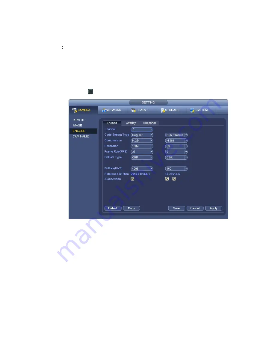
Quality: There are six levels ranging from 1 to 6. The sixth level has the highest image quality.
Video/audio: You can enable or disable the video/audio. Please note, once you enable audio
function for one channel, system may enable audio func tion of the rest channels by default.
Copy
After you complete the setup, you can click Copy button to copy current setup to other
channel(s). You can see an interface is shown as in Figure 4-44. You can see current channel
number is grey. Please check the number to select the channel or you can check the box ALL.
Please click the OK button in Figure 4-44 and Figure 4-42 respectively to complete the setup. Please
note, once you check the All box, you set same encode setup for all channels. Audio/video enable
box, overlay button and the copy button is shield.
Please highlight icon
to select the corresponding function.
Figure 4-41
4.7.1.2 Overlay
Click overlay button, you can see an interface is shown in Figure 4-42.
Cover area: Here is for you to cover area section. You can drag you mouse to set proper section size.
In one channel video, system max supports 4 zones in one channel. You can set with Fn button or
direction buttons.
Preview/monitor: The cover area has two types. Preview and Monitor. Preview means the privacy
mask zone can not be viewed by user when system is in preview stat us. Monitor means the privacy
mask zone can not be view by the user when system is in monitor status.
Time display: You can select system displays time or not when you playback. Please click set button
and then drag the title to the corresponding position in the screen.
Channel display: You can select system displays channel number or not when you playback. Please
click set button and then drag the title to the corresponding position in the screen.
Содержание NVR-1001U
Страница 1: ...i NVR xU NVR xUD Network video recorder User s manual...
Страница 32: ...23 3 4 Connection Sample Figure 3 3...
Страница 87: ...147 Figure 4 74 Figure 4 75...
Страница 88: ...148 Figure 4 76 Figure 4 77...
Страница 94: ...154 Figure 4 82 Figure 4 83...
Страница 95: ...155 Figure 4 84 Figure 4 85...
Страница 96: ...156 Figure 4 86 Figure 4 87...
Страница 98: ...158 Figure 4 89 Figure 4 90...
Страница 101: ...161 Figure 4 92 Figure 4 93 4 11 1 1 Connection The connection setup interface is shown as in Figure 4 94...
Страница 121: ...181 Figure 4 116 In Figure 4 116 click one HDD item the S M A R T interface is shown as in Figure 4 117 Figure 4 117...
Страница 136: ...196 Figure 4 136 Figure 4 137 4 14 3 1 Add Modify Group...
Страница 176: ...236 Figure 5 53 Figure 5 54...
Страница 177: ...238 Figure 5 55 Figure 5 56 Figure 5 57...
Страница 181: ...242 Figure 5 61 Figure 5 62...


