5.2
Window structure
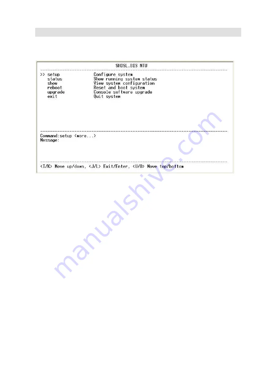
After you type the password, it will display the main menu.
Above captured screen shows the common structure for all windows used throughout the configuration console
terminal.
From top to bottom, the window is divided into four major sections.
The very top line displays the product name as “SHDSL.BIS NTU”.
Next a block of commands is listed where the ">>" symbol indicates the current cursor placeholder.
The next block down is the "command" section. The command that is selected and ready for execution is displayed
after the "Command:" prompt. The "<more…> designation indicates that there are other sub menus for this
command. The "Message:" field is used to display any special system messages or warnings.
Finally, at the very bottom of the screen is a help command line and reminder of the currently available command
keys. In most cases, the keyboards four cursor keys can be used to navigate all the menu system. If for some reason
your keyboard's cursor keys are not supported in the terminal emulation software, you may use the keys listed on
the help command line.
Menu Commands
Before changing the configuration, familiarize yourself with the operations listed in the following table. The operation
list will be shown on the window.
Содержание G.SHDSL .bis NTU Series
Страница 1: ...G SHDSL bis NTU XL GDB 102Ev3 User Manual Version 0 08 ...
Страница 8: ... Operation temperature 0 to 45 C Humidity Up to 95 non condensing External screw for frame grounding ...
Страница 9: ...1 3 Applications ...
Страница 11: ...2 1 Front Panel 2 1 1 E1 T1 interface model 2 1 2 Serial interface model 2 1 3 Ethernet interface model ...
Страница 23: ...2 3 1 E1 T1 Interface AC power input version DC power input version ...
Страница 24: ...AC DC dual power input version Use DC input only ...
Страница 25: ...2 3 2 Serial Interface AC power input version DC power input version ...
Страница 26: ...AC DC dual power input version Use DC input only ...
Страница 27: ...2 3 3 Ethernet Interface AC power input version DC power input version ...
Страница 37: ......
Страница 40: ...3 4 1 Show Statistic on E1 Interface ...
Страница 41: ...3 4 2 Show Statistic on Serial Ethernet T1 Interface ...
Страница 42: ...3 5 Menu tree for SYSTEM SETUP You can setup 11 interface modes via LCD display ...
Страница 50: ...3 5 4 Sub Menu tree for SETUP SERIAL Interface SYSTEM SETUP SETUP SERIAL ...
Страница 74: ...For Serial interface model For Ethernet interface model ...
Страница 75: ......
Страница 76: ......
Страница 84: ...Menu tree The item according to which interface modes you have setup ...
Страница 86: ...5 4 1 Configure NTU Interface Setup Interface ...
Страница 123: ...press CTRL C to quit 5 6 2 View the Interface status Select Interface command to show the status of Interface ...
Страница 134: ...For Ethernet interface mode For E1 and Serial interface mode ...
Страница 136: ...For E1 interface mode For T1 interface mode ...
Страница 137: ...For Serial interface mode For Ethernet interface mode ...
Страница 138: ...For E1 Serial interface mode For E1 Ethernet interface mode ...
Страница 141: ...When it is upgrading you can see the following ...
Страница 147: ...The new login screen will be shown again you can type username and password again to enter ...
Страница 152: ...The front view of DB 25 F Serial interface connector on rear panel ...
Страница 154: ......


