148
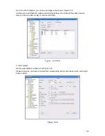
Figure 7-47
Important
The alarm output port should not be connected to high power load directly (It shall be less than
1A) to avoid high current which may result in relay damage. Please use the co contactor to
realize the connection between the alarm output port and the load.
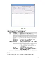
Please refer to the following sheet for detailed information.
Parameter
Function
Alarm output
There are three output channels (Multiple choices).
Please note the displayed alarm output channel amount here may
vary due to the different series.
Activate
Enable/disable alarm output device. After the Web activated the
alarm, you need to cancel the channel and then click the
activation button to cancel the alarm, or you need to cancel the
alarm in the pop-up dialogue box in local-end.
Refresh
Search alarm output status.
7.3.3.3 Record
Record control interface is shown as in Figure 7-48.
Содержание DVR-470
Страница 1: ...1 DVR 470 870 1670 PK User s Manual...
Страница 8: ...8 APPENDIX G EARTHING 175 APPENDIX H TOXIC OR HAZARDOUS MATERIALS OR ELEMENTS 180...
Страница 32: ...32 2 3 3 2U series Please refer to Figure 2 10 for connection sample Figure 2 9...
Страница 52: ...52 1U series 1 5U Series...
Страница 53: ...53 2U Series Figure 3 11...
Страница 68: ...68 Figure 4 21 Figure 4 22 Figure 4 23 4 5 3 Video Loss Figure 4 24...
Страница 71: ...71 Figure 4 27 Figure 4 28 Figure 4 29 Figure 4 30...
Страница 115: ...115 Figure 6 11...
Страница 171: ...171 Samsung HA101UJ CE 1T SATA...


