


-10-
Setting Camera Resolution
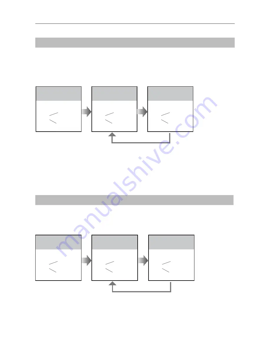
Setting Unlock Mode
The resolution of the camera can be adjusted at any time, that means the quality of image on
screen can be set to high or low.
High resolution is default, to change the setting, please follow the steps:
There are 2 unlock modes,
Normally opened
and
Normally closed
.
Normally opened is default, to change the setting, please follow the steps:
UNLOCK Indicator:OFF
TALK Indicator:ON
Buzzer
Beep+, Beep
In standby mode, press
KEY_SET
button twice.
UNLOCK Indicator:OFF
TALK Indicator:ON
Buzzer
Beep+
Press
KEY_2
button to set the
camera to
High
resolution.
UNLOCK Indicator:OFF
TALK Indicator:ON
Buzzer
Beep, Beep
Press
KEY_2
button again
to set the camera to
Low
resolution.
Press
KEY_2
UNLOCK Indicator:ON
TALK Indicator:OFF
Buzzer
Beep+, Beep
In standby mode, press
KEY_SET
button
three
times
.
UNLOCK Indicator:ON
TALK Indicator:OFF
Buzzer
Beep+
Press
KEY_1
button to set
the unlock mode to
Normally opened
.
UNLOCK Indicator:ON
TALK Indicator:OFF
Buzzer
Beep, Beep
Press
KEY_1
button again
to set the unlock mode to
Normally closed
.
Press
KEY_1
SETUP INSTRUCTIONS
•
If setting mode has not been exited, you can change the camera resolution by pressing KEY2 circularly.
•
The
LED_NAME
indicator will blink all the time until exit out the setting mode.
•
If without any operation in 10 seconds, it will exit out setting mode automatically.
•
In this step,press
KEY_SET
button three times to exit out the setting mode manually.
•
If setting mode has not been exited, you can change the unlock mode by pressing KEY1 circularly.
•
The
LED_NAME
indicator will blink all the time until exit out the setting mode.
•
If without any operation in 10 seconds, it will exit out setting mode automatically.
•
In this step,press
KEY_SET
button twice to exit out the setting mode manually.


