2 WIRE SYSTEM
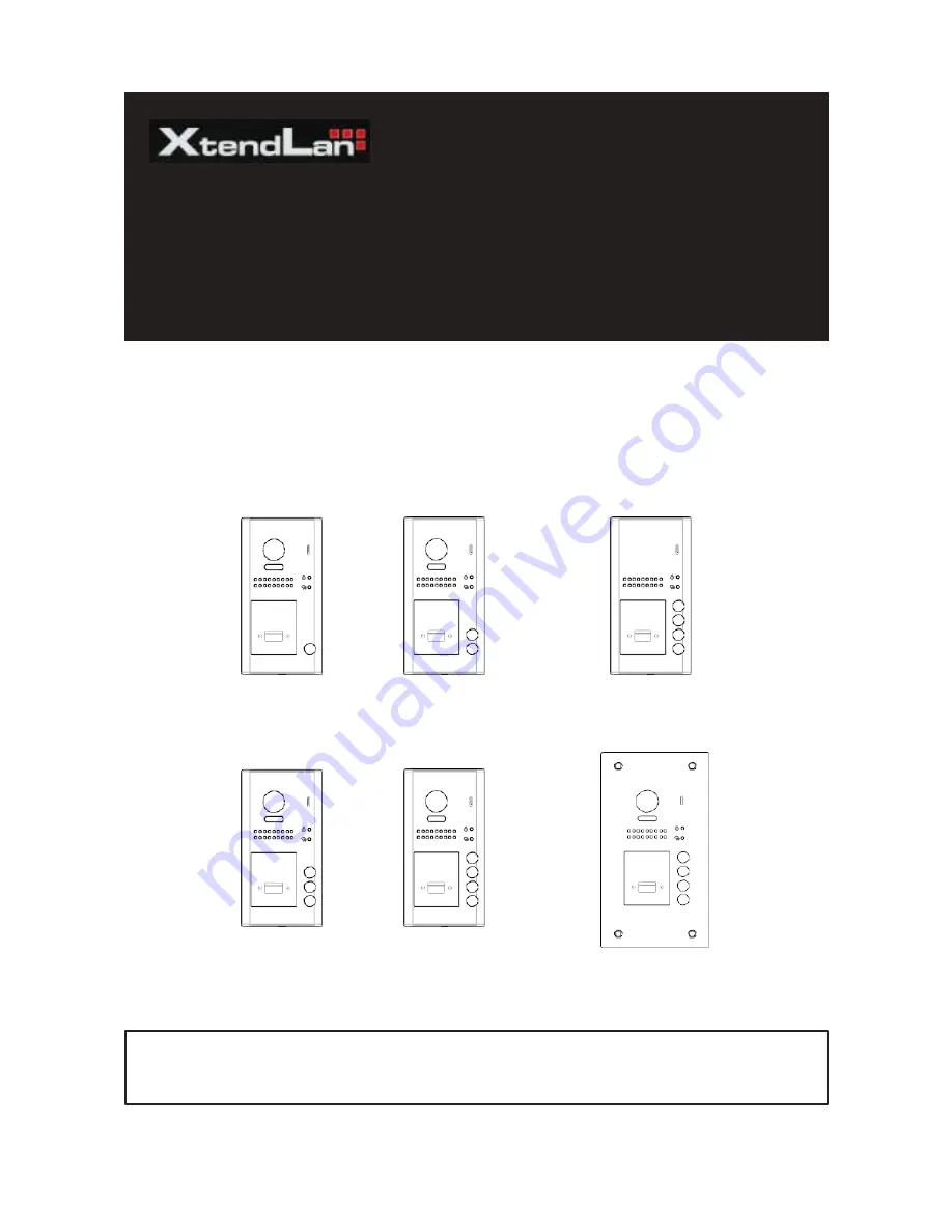
XtendLan DPC-D250 series
A door station with proximity access control
USER MANUAL
RF CARD
RF CARD
RF CARD
RF CARD
RF CARD
RF CARD
• Please read this manual carefully to ensure safe and correct operation.
• Keep this manual well for future reference.


