


Section 1 – Description of the device
1.1 Purpose
The unit is designed for controlled supply and exhaust ventilation of frost-free rooms within a building.
Model 180 Series
is used for domestic properties with 1 kitchen and up to 3 additional wet rooms (K + 3).
Model 350 Series
is used for domestic properties with 1 kitchen and up to 7 additional wet rooms (K + 7).
(“Wet rooms” include bathrooms, toilets, ensuites, etc).
The air flows through air ducts.
Connecting exhaust hoods to the ventilation system is not permitted. The unit is not to be used as a
dehumidifier.
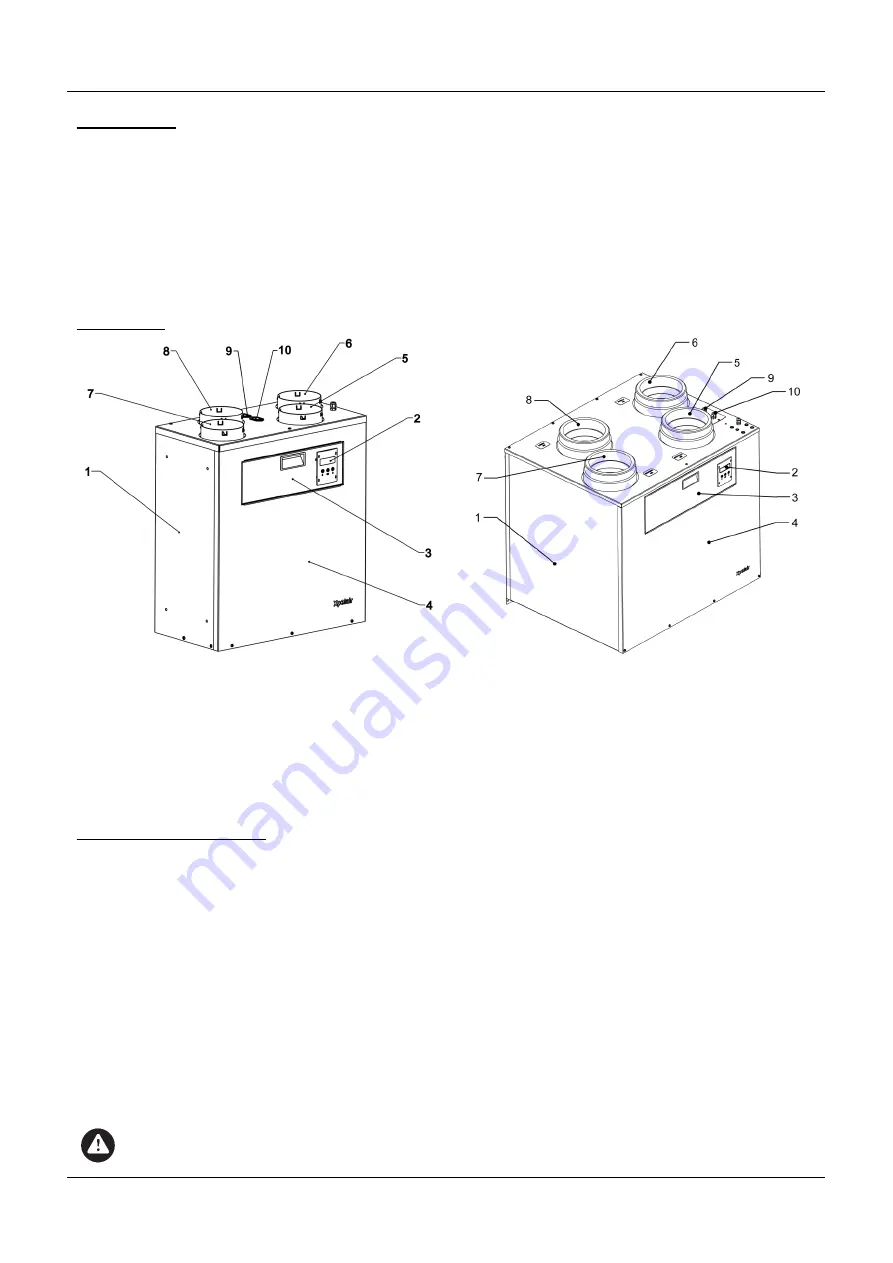
1.2 Design
Fig. 1.1a Structure of the Natural Air 180
Fig. 1.1b Structure of the Natural Air 350
1 Back plate and sides
2 Control panel and display
3 Inspection door
4 Front cover
5 Connection nozzle, extract air
6 Connection nozzle, supply air
7 Connection nozzle, exhaust air
8 Connection nozzle, fresh air
9 Defrost Heater supply output (PH variants only) *
10 Boost Heater supply output (PH variants only) *
* External Heater boxes (not supplied) are available
as an accessory. (See User Manual for details).
1.3 Operating principle
The unit is fitted with two fans using energy-saving “EC” technology which carries out a controlled air
exchange in applicable buildings.
Used air is drawn in to the unit as Extracted air from the rooms with the highest air humidity and odour (e.g.
bathroom and kitchen) and is transferred to the outside as Exhaust air via a system of air ducts.
At the same time, a second duct system takes in Fresh air from outside the building and transfers it into living
rooms and bedrooms as Supply air.
Both air flows are completely separate and are passed through a heat exchanger which recovers waste heat
from the extracted air to warm up the supply air. This ensures that the majority of heat is kept in the building.
An internal bypass can be opened so that fresh air is supplied to the intake rooms without being warmed up
by the heat exchanger. Heat recovery is disabled in this case.
Halls and corridors normally act as transfer areas in which the air from the supply areas flows into the extract
areas. Undercut doors and air transfer grilles are used so that the air flow between rooms is not restricted.
WARNING:
Ensure free access to the unit and to the switch disconnecting it from the power supply at all times.
3