background image

Alignment instructions


1. Test equipment 

Digital multimeter, signal generator (54200) 
PC set (FLASH writing programs and W24CXX.EXE have to be installed first,) 
VG849 (HDMI signal generator) 
CA210 (White balancer), DVD player(with HDMI output), monitor 

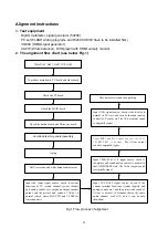
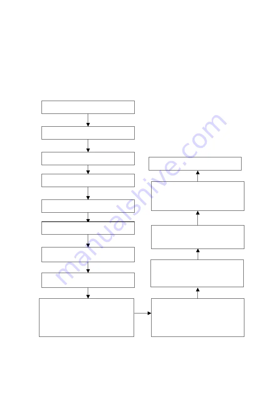
2. The alignment flow chart (see below Fig.1) 


Fig.1 Flow process of alignment 


Check accessories and then packing 

Write N105, N403, N607, N70, N606 

To produce main board, TV board and other board

Check the MAIN board 

Check the buttons board and IR receive board

Combined test for general assembly 

Input AV1/S/AV2 signal source, check if the
various terminal functions (system identify and
analog control etc.) and the picture and sound of
AV-out is normal. (S-terminal shares the same
audio channel with AV1, and it can be auto
identified) 

Check the TV board 

Input YPbPr/YCbCr 1/2 signal source; check if
the picture and sound analog control is normal in
the COMPONENT state. The AV-out output sound
is originally signal 

Input HDMI and DVI signal source, check if
the HDCP KEY is normal. 

The AV-out output

sound is originally signal 

Input VGA signal source, check is the display is
normal in PC state and various function (analog
control) H-V center etc. The AV-out output sound
is originally signal 

Aging 

Input the center signal source, check if various
functions of TV (search channel, system identify
and analog control etc.), earphone output, speaker
output and the picture and sound of AV-out is
normal. (check stereo/SAP, CCD and VCHIP for
American unit) 

ADC correction and white balance adjustment

Содержание LC-40T7

Страница 1: ...LCD TELEVISION LC 40T7...

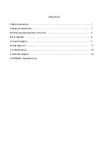
Страница 2: ...TS Safety precautions Alignment instructions Working principle analysis of the unit Block diagram IC block diagram Wiring diagram Troubleshooting Schematic diagram APPENDIX Exploded View 1 3 6 8 9 17...

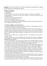
Страница 3: ...will result 2 5 If any foreign substance such as water liquid metal slices or other matters happens to fall into the module be sure to cut the power off immediately and do not move anything on the mod...

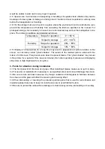
Страница 4: ...of picture residue on the screen as commonly called ghost shadow The extent of the residual picture varies with the maker of LCD screen This phenomenon doesn t represent failure This ghost shadow may...

Страница 5: ...nd sound of AV out is normal S terminal shares the same audio channel with AV1 and it can be auto identified Check the TV board Input YPbPr YCbCr 1 2 signal source check if the picture and sound analo...

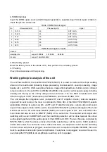
Страница 6: ...of AV OUT should be the sound of the current channel but the picture don t need to check 3 4 the unit adjustment After install the unit check it is normal working 3 5 Aging a Select the TV channel th...

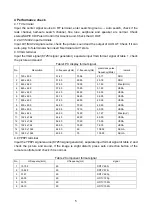
Страница 7: ...480 31 50 60 00 25 18 DOS 3 640 x 480 37 90 72 00 31 50 Mac SOG 4 640 x 480 37 50 75 00 31 50 VESA 5 640 x 480 43 30 85 00 36 00 VESA 6 800 x 600 35 16 56 25 36 00 VESA 7 800 x 600 37 90 60 00 40 00...

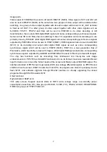
Страница 8: ...U correlates with each other through pin 14 INT interruption of ATMEGA8L pin 28 and 29 SDA SCL This unit adopts the integrative tuner contains HF and IF amplifier circuits antenna reception signal wil...

Страница 9: ...rresponding synchronous signal which will be sent to PW218 N601 PW218 is a new generation chip of Pixelworks which has ability to deal with images 24bit digital RGB signal and some corresponding synch...

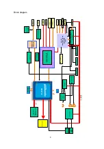
Страница 10: ...2 I2C2 KEY E2PROM PW2300 HDMI AD9880 or AD9398 PC YPbPr2 Audio Tuner YPbPr1 Audio RF Video RF Audio I2C1 AV1 AV2 memory LM4808 TPA3008D2 MSP3425 STERO SAP decoder Earphone socket with switch PC Audio...

Страница 11: ...have HDMI digital and analog terminal of working frequency 165Hz it support 1080P non interlaced scanning and UXGA 1600 x 1200 60Hz video format also it support eight audio channel of 192KHz AD9398 w...

Страница 12: ...verter output 49 DDC_CLK HDCP Slave Serial Port Data Clock 92 99 GRE 0 7 Converter output 50 DDC_DATA HDCP Slave Serial Port Data I O 20 21 MCLK Control clock output 51 MCL HDCP Master Serial Port Dat...

Страница 13: ...eo decoder and three highly velocity AD converter chip It supports HDTV NTSC PAL and SECAM Its analog port support 1080P 150MHz Internal Block Diagram PW2300 PINS FUNCTION Pin Name Function Pin Name F...

Страница 14: ...N4 B_1 AV1 blue input G15 G_DLK Clock output GBO 2 9 Blue odd pixel data output GBE 0 7 blue even pixel data output GGO 2 9 greed odd pixel data output GGE 0 7 greed even pixel data output GRO 2 9 red...

Страница 15: ...udio output for left channel 4 V2P5 2 5V Reference for analog cells 27 ROSC I O current setting resistor for ramp generator 5 LINP Positive audio input for left channel 41 ROUTP Positive audio output...

Страница 16: ...Pin Name Description 3 HD2_L Audio input 5 HD2_R Audio input 6 AV1_L Audio input 8 AV1_R Audio input 9 AV2_L Audio input 11 AV2_R Audio input 27 TV_L Audio input 25 TV_R Audio input 24 Left audio chan...

Страница 17: ...ync output1 8 BYP Bypass capacitance 15 SYNC_IN2 Sync intput2 9 DDC_OUT1 DDC output 16 SYNC_OUT2 Sync output2 10 DDC_IN1 DDC _output1 7 MSP3425 The MSP 34X5G family of single chip Multistandard Sound...

Страница 18: ...16 Pin description Pin Description Pin Description 2 SIF IN 29 AVOUT_R 12 I2C_CL 30 AV OUT_L 13 I2C_DA 40 SC1_IN_L 25 OUT_R 41 SC1_IN_R 26 OUT_L 42 VEEFTOP 43 MONO_IN...

Страница 19: ...03 X608 TUNER X601 X101 X401 X402 X8 X7 XA01 CN2 CN3 CN4 CN5 CN1 RS 232C HDMI VGA VGA AUDIO IN S VIDEO AC220 Speaker HEADPHONE KEY BOARD Remote receiver X60 2 X607 X605 X606 X601 X300 X700 X502 X501 L...

Страница 20: ...d if interfered possibly by the equipment like transmitting antenna non professional radio station and cellular phone 1 2 TV set Symptoms Possible cause Unable to switch the power on Check to see if t...

Страница 21: ...batteries are installed in the reverse order Check if the battery is effective Check the distance or angle from the monitor Check if there is any obstruct between the remote control and the TV set Che...

Страница 22: ...m 10mm 5mm Total defected point 8 7 5 4 Notes 1 Definition of defected point bright spot dark spot It is identified as a defected point if its area exceeds 1 2 of a single picture element R G B 2 Defi...

Страница 23: ...eck the 5V STBY Cut off the the power board and video board to main board check it Power board problem Check the supply power 3 3V Short circuit the pin 1 STANDBY of X604 to 5V then check the supply p...

Страница 24: ...X4 Unfix X3 and X4 turn on the unit and check if display the white screen Check input signal of N601 and power supply Check the supply power 120 of backlight board N601 damaged Check N201 and the circ...

Страница 25: ...m Yes No No Yes No Yes Sound power amp or other peripheral circuit have problem Check power supply if SHUTDOWN pin control is normal and if output short circuite or other problems that cause protectio...

Страница 26: ...k main board Check whether C527 is 16V Check whether IC N508 is damaged Check whether pin7 and pin3 of X505 in power board are 18V and 5V Check whether C511 is 18V Check whether IC N501 is damaged Che...

Страница 27: ...PDF pdfFactory Pro www fineprint com cn...

Страница 28: ...PDF pdfFactory Pro www fineprint com cn...

Страница 29: ...PDF pdfFactory Pro www fineprint com cn...

Страница 30: ...PDF pdfFactory Pro www fineprint com cn...

Страница 31: ...PDF pdfFactory Pro www fineprint com cn...

Страница 32: ......

Страница 33: ......

Страница 34: ......

Страница 35: ......

Страница 36: ...42 Power board...

Страница 37: ...603 L40T70 10 Ver 1 0...

Отзывы: