Xo 250 Скачать руководство пользователя страница 9

16 


 17

The pump drains the bilge when its surface sensor detects water in 
the bilge. As long as the battery is connected and regardless of the 
position of the main power switch, the automatic pump is always 
on standby. The bilge pump will start only after the sensor has been 
completely submerged for 5 seconds and stop once the water level 
has fallen completely below the sensor. You can also activate the 
pump manually from a spring-loaded switch on the control panel. 
The suction inlet of the electrical bilge pump must be checked regu-
larly and cleaned of debris when necessary. You can access the 
pump through the service hatch in the engine well.

CAUTION! 

The bilge pump system is not intended for managing leaks resul-
ting from running aground or other damage.

NOTE!

Before setting off, check the amount of bilge water by draining 
the bilge manually using the spring-loaded switch on the control 
panel. It is the user’s responsibility to keep at least one bucket 
or bail in the boat.

NOTE! 

Check the operation of the bilge pump regularly. If you find that 
the bilge pump does not work correctly, clean the pump suction 
inlet of debris and, if necessary, contact your XO dealer.

5.6.3 Stability, buoyancy and flotation

Thanks to its optimal hull shape and weight distribution, the XO boat 
has an excellent stability. However, please remember that large 
crashing waves pose a significant danger to stability. Note also 
that the boat’s stability will decrease if any large load is positioned 
high up in the boat. All changes in weight distribution can seriously 
affect the boat’s stability, trim and performance. If you are planning 
on such changes, please contact the manufacturer. The amount of 
water in the bilge must be kept to a minimum, as water flowing freely 
within the boat will always reduce stability. Possible loss of stabi-
lity when towing or being towed should also be taken into account.

 
5.7 FIRE OR EXPLOSION RISK PREVENTION

5.7.1 Engines and fuel systems

The XO 250 Open has a fixed fuel tank amidships in the boat’s bilge 
compartment. Before refuelling, turn off the engine and put out 
cigarettes and any open flames. Do not use any electrical equip-
ment. There is a fuel fill inlet on both sides of the boat above the 
scuppers. Lift reserve fuel canisters from the boat for filling to 
avoid spilling fuel in the bilge. When refuelling at a fuel station, do 
not use a plastic funnel, as it would prevent static electricity bet-
ween the dispenser nozzle and tank inlet from releasing. After fil-
ling the tank (for the tank capacity, see Appendix 1 ‘Technical spe-
cifications’), check that no fuel has leaked into the bilge or engine 
compartment, and immediately remove any spilled fuel. Do not 
store reserve fuel canisters in unventilated spaces or without 
securing them, nor any equipment containing petrol in areas not 
intended for fuel storage.  Check the fuel hoses for wear annually.

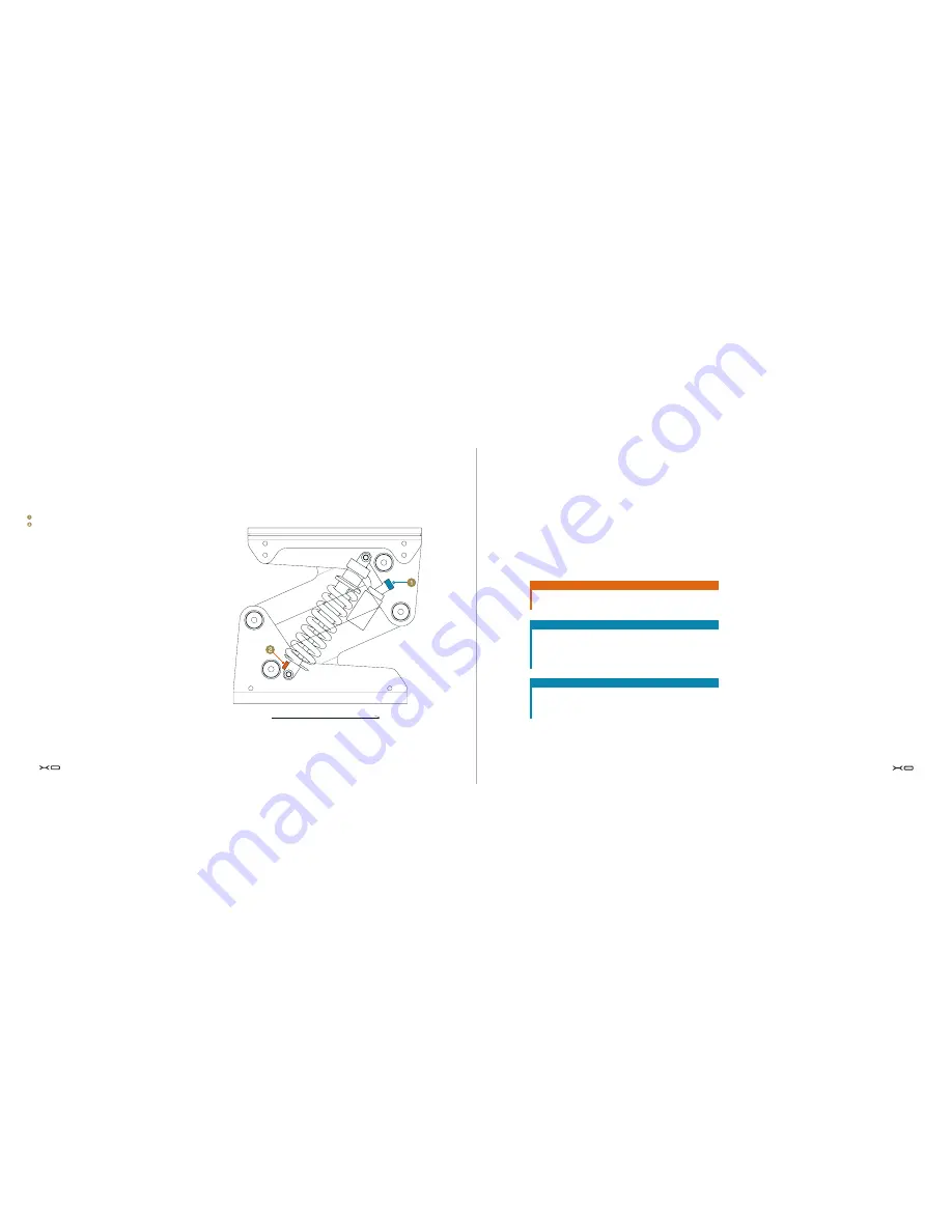
Seat suspension adjustment

(Figure 3)

 Suspension stiffness adjustment 
 Suspension rebound speed adjustment

Sitting direction

Содержание 250

Страница 1: ......

Страница 2: ...ng the boat before taking command Your boat dealer as well as boat clubs and national motor boat and yacht associations are more than happy to tell you about local boat training programmes and recomme...

Страница 3: ...nd prevention 18 5 8 Electrical system 19 5 9 Steering properties 23 5 9 1 Driving at high speeds 23 5 9 2 Emergency switch 24 5 9 3 Visibility from the steering position 24 5 10 Correct use other rec...

Страница 4: ...purchase II OWNER First name Surname Municipality of domicile Year of purchase III OWNER First name Surname Municipality of domicile Year of purchase IV OWNER First name Surname Municipality of domic...

Страница 5: ...fuel than required in case of exceptional and unfo reseen circumstances Engine and equipment Check the operation and condition of steering electrical devices and battery and perform all daily inspecti...

Страница 6: ...as follows DANGER If appropriate precautions are not taken there is a serious risk which will very probably lead to death or permanent injury CAUTION If the appropriate precautions are not taken ther...

Страница 7: ...and operate the boat appropriately 5 2 BASIC SPECIFICATIONS The basic specifications of the XO 250 Open are as follows Boat type XO 250 Open Design category C inshore Maximum allowed load 848 kg Pleas...

Страница 8: ...centre 5 6 STABILITY AND PREVENTING WATER INTAKE 5 6 1 Openings in hull and deck The XO boat does not have a plug for draining the cockpit Instead the cockpit is drained through scupper valves attach...

Страница 9: ...Note also that the boat s stability will decrease if any large load is positioned high up in the boat All changes in weight distribution can seriously affect the boat s stability trim and performance...

Страница 10: ...serve fuel canister can be sto red in the position reserved for the heater s reservoir leave the boat unattended when the boiler or heater is on 5 8 ELECTRICAL SYSTEM The wiring diagram for the boat s...

Страница 11: ...light white 360 Navigation lights red and green Control panel Power socket 12 V 10 A max Fuse box see figure 7 Windscreen wiper CONTROL DEVICES Figure 6 Control panel Bilge pump activation switch Sign...

Страница 12: ...boat is 221 kW 300 hp Do not use the boat if it has an engine with a higher power rating than that indicated on the builder s plate Use the engine s electro hydraulic power trim feature as follows Whe...

Страница 13: ...ibility from the steering position When the weather is calm and beautiful the boat is easy to ope rate Just remember to arrange the proper look out as required by the COLREG regulations Always make su...

Страница 14: ...have sub stantially better traction if the first 3 5 meters of the anchor line is made of either chain or weighted rope CAUTION Do not try to stop the boat with your hands only nor place your hand or...

Страница 15: ...transport Pro tect the boat by placing padding between the boat and the straps where chafing may occur Check the engine s manual for additional instructions concerning trailer transport Also remember...

Страница 16: ...be installed in the boat place non conduc tive washers between the surface treated aluminium surface and the surface in contact with the aluminium either the accessory s installation surface or screw...

Страница 17: ...h targa arch above waterline 2 40 m the exact vertical clearance should be checked for each individual boat draught 0 90 m Weight specification outboard model Light weight 1 897 kg Displacement at ful...

Страница 18: ...on the following page I hereby declare that the recreational craft specified above satis fies the relevant safety requirements according to the specifica tion provided on the following page and the E...

Страница 19: ...g position RSG Guidelines EN ISO 11591 2000 Engine identification Engine CE marked Noise emission level Engine CE marked APPENDIX 3 GENERAL REQUIREMENTS APPENDIX 4 ELECTRICAL WIRING DIAGRAM 38 LIITE 5...

Страница 20: ...5 BLUE RED 1 RED NAV COMP_L_OUT 4 BLACK INPUT 4 BLACK INPUT 1 BLACK INPUT 1 5 BLACK 1 BLACK FIRE_EXT 1 RED 1 RED FIRE_IND 1 RED FIRE_IND 1 RED ANC_L_OUT 1 BLACK 1 5 BLACK 1 BLACK 40 Project rev Sheet...

Страница 21: ...TTER 1 5 BLUE PLOTTER 1 5 BLACK INPUT 1 5 BLACK INPUT 2 5 BLACK INPUT 1 5 BLACK INPUT 1 5 WHITE ENG_BL_IN 1 5 WHITE ENG_BL_OUT 1 5 WHITE 1 5 WHITE 25 BLACK 16 RED 25 RED 16 RED 1 5 BLACK INPUT VSR_2ND...

Страница 22: ...22 400 mm TAM 26 600 mm TAM 26 1600 mm TAM 16 1500 mm TAM 16 1900 mm TAM 16 1700 mm TAM 16 2900 mm TAM 16 1700 mm 1800 mm 1 RED 1 RED 1 5 GREEN BLACK 1 5 BLACK 1 RED 1 BLACK 1 5 BROWN 2 5 BLACK 1 RED...

Страница 23: ...2 ENG_BL_OUT X 11 3 M4 1 INPUT X 11 4 TAM 16 3700 mm TAM 16 2400 mm TAM 16 3700 mm 3800 mm 2500 mm 3800 mm 1 5 LIGHT RED 1 5 BLACK 1 5 WHITE 1 5 BLACK 1 RED 1 BLACK 1 BLACK 1 RED 1 5 LIGHT RED 1 5 BLA...

Страница 24: ...S1d 1 70 10 M_F6a 1 10 INPUT M6a 1 70 10 M_F6b 1 70 RED 3000 mm 70 RED 700 mm 70 BLACK 4500 mm TAM 22 2900 mm TAM 22 600 mm TAM 22 4400 mm 48 Project rev Sheet rev Drawing by Date Modified by Descript...

Страница 25: ...0 F 12 1 1 INPUT F3 1 X 2a 1 8N BACK VIEW 2 INPUT F8 1 3 FIRE_IND F6 2 4 NAV ANC_L_IN F1 2 5 TRIM F2 2 6 HORN_IN F3 2 7 OUTLET F4 2 8 RADIO F5 2 2634810 1 WIPER_SB_IN C F7 2 X 2b 1 8N BACK VIEW 2 WIPE...

Страница 26: ...1 3 HORN HORN_OUT X 6a 6 M22 K10 4 AUX CAB_L_IN X 6c 1 S2 1 1 3 AUX AUX CAB_L_OUT X 6c 7 M22 K10 4 WIPER_SB_IN C S4 2 3 X 6b 1 S4 1 1 3 WIPER STB WIPER_SB_I X 6b 7 M22 K10 4 WIPER_SB_IN C S4 1 3 S4 2...

Страница 27: ...OUT H29 X 3 1 2NT BACK VIEW 2 INPUT H29 2637710 AUX CAB_L_OUT X 3 1 H31 H29 1 INPUT X 3 2 H31 Lt1 AUX CAB_L_OUT H32 H29 H31 1 INPUT H32 H29 Lt1 AUX CAB_L_OUT H33 H31 H32 1 INPUT H33 H31 Lt1 AUX CAB_L_...

Отзывы: