background image

18


X

X

N

N

E

E

T

T


N

N

e

e

t

t

w

w

o

o

r

r

k

k


B

B

o

o

x

x


C

C

a

a

m

m

e

e

r

r

a

a


I

I

n

n

s

s

t

t

a

a

l

l

l

l

a

a

t

t

i

i

o

o

n

n


M

M

a

a

n

n

u

u

a

a

l

l


NETWORK

 : This Ethernet terminal connects to 10Mbps or 100Mbps LAN through an RJ-45 connector. 

When optional PoE is used, the power will be supplied from the Network Cable.   

„


LINK : Yellow light indicates that he network is properly connected.   

„


ACT : Green light indicates that the XNET system connected to 100Mbps LAN. This green lamp will 
blink if the system receives data. 


STATUS LED

 : Indicates the operation status 

„


EVENT LED : Green light indicates that Alarm Out signal is turned on. 

„


POWER LED : Red light indicates that 12V DC power is connected.   


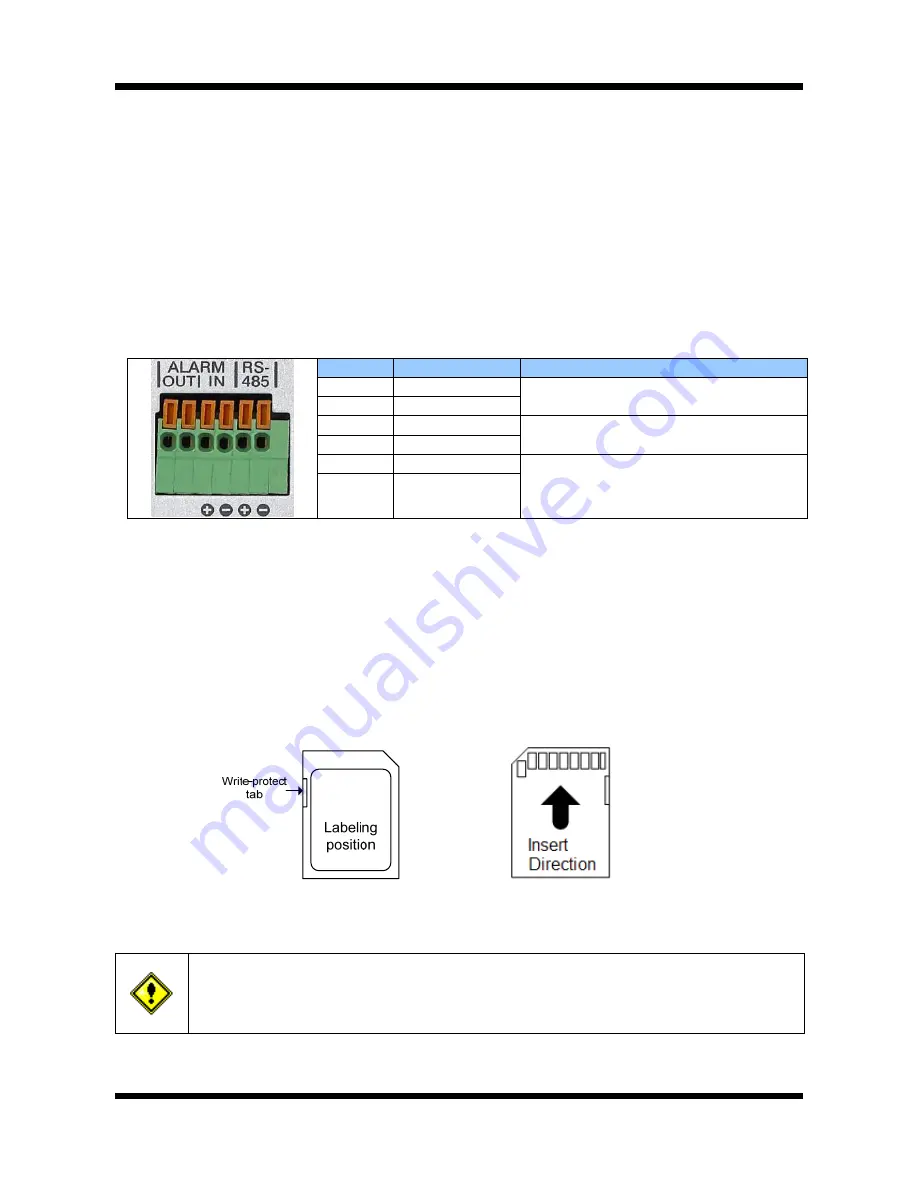
RS-485 and ALARM In/Output Terminal   

Pin 

Description 

Set up 

1 Alarm 

Out 

Select NC/NO at menu screen 

2 Alarm 

Out 

3 Alarm 

In(+) 

Select NC/NO at menu screen 

4 Alarm 

In(-) 

5 RS485 

6 RS485 


„


RS-485

: When properly connected, you can remotely control Pan/Tilt device with RS-485 control 

interface. 

„


Alarm In

: This connects to an Alarm Sensor signal. Only one sensor can be connected.   

„


Alarm Out

: This connects to an external Alarm device that operates by a relay such as Siren       

Lamp or Alarm Light. Only one Alarm device can be connected.   


SD CARD SLOT

 : Enables recording of video data to an external memory device upon occurrence of an 

event. Please use less than 4 GB SD Memory. 


Figure 2-4. SD CARD 


Power Terminal: 

Connect 12V DC Power to this terminal.


Do not use this connector when powering up the product through LAN cable. (PoE)     
The product is not covered under warranty when it is damaged by connecting both 

Ethernet power and 12V DC power to this terminal. 


1                          6 

Содержание IGB1110PF

Страница 1: ...Ver 1 0 XNET Network Box Camera IGB1110PF IGB1110NF Installation Manual...

Страница 2: ...rer immediately if you think there is any problem with the product Contact the store or the manufacturer before disassembling the product for alteration or repair XNET is a trademark of CNB Technology...

Страница 3: ...ct 5 2 1 Contents 5 2 2 Product Information 5 2 3 Functions and Designations 6 2 3 1 Side View 6 2 3 2 Rear View 7 2 3 3 Connecting to Alarm devices 9 3 Software Installation 10 3 1 Connecting XNET to...

Страница 4: ...pplications of network or user 2 way Audio Communication Bi directional voice communication between Client s PC and XNET Smart Event feature On the top of motion detection and sensor alarm feature pre...

Страница 5: ...Camera Lens not included Auto Iris Lens Plug Connection plug for Auto Iris control signal Power adapter Input 100 240VAC 50 60Hz Output 12VDC 2A AC power Cord 2 jack cable CD Software and User s manua...

Страница 6: ...ount Fixed or Vari Focal DC Auto Iris lens yAuto Iris Control Plug Plug for Auto Iris control The following shows each pin connection Strip 8mm of outer jacket of the lens cable and then strip 2 mm of...

Страница 7: ...r Amplified device or Speaker This can be used to listen to the audio signal sent from a remote PC for Bi directional Audio communication VIDEO OUT Use this output to monitor the analog video signal w...

Страница 8: ...in Description Set up 1 Alarm Out Select NC NO at menu screen 2 Alarm Out 3 Alarm In Select NC NO at menu screen 4 Alarm In 5 RS485 6 RS485 RS 485 When properly connected you can remotely control Pan...

Страница 9: ...shown in figure 2 5 NC or NO of sensor input can be selected at Menu screen Alarm Sensor device requires a separate power source Alarm in Alarm in Photo Coupler Sensor Device Signal 5 30VDC GND Adapt...

Страница 10: ...rk k 1 A PC or a laptop computer is required to set up an IP address z Compatible operating system Windows 2000 Windows XP Windows Vista z Since the default IP address of the device is 192 168 123 10...

Страница 11: ...a and monitoring PC to a network IP Installer software provided in the Installation CD included in the package and also available to download from our website http www cnbtec com will configure IP add...

Страница 12: ...h you wish to change the IP address and click Set IP Address button to bring up the following box in Figure 3 3 Figure 3 3 IP Address box 3 When you enter the IP address and click Set button the box s...

Страница 13: ...T CMS software This manual explains about using internet web browser only For instructions on how to configure network connection using XNET CMS software please refer to XNET CMS Manual which can be f...

Страница 14: ...http 192 168 123 100 8080 Address format for accessing as an administrator When using default IP address and port number http 192 168 123 100 When IP address and port number changed http IP address n...

Страница 15: ...k B Bo ox x C Ca am me er ra a I In ns st ta al ll la at ti io on n M Ma an nu ua al l 4 4 2 2 W We eb b V Vi ie ew we er r P Pa ag ge e Web viewer page consists of Video monitor screen and menu opti...

Страница 16: ...IP camera and control of PTZ movement Please refer to XNET Owner s Manual for detail Motion Detection Opens up Motion Detection page You can add or delete areas for detecting motion in this page Plea...

Страница 17: ...ol On Off 8 zone settings over IP Stabilizer On Off D Effect V Flip Mirror Rotate Electronic Shutter Speed 1 60 1 90 000 Sec 1 50 1 90 000sec Video Audio Compression MJPEG MPEG4 H 264 Frame rate Singl...

Страница 18: ...cal storage Internal memory or SD card memory JPEG image Applications Browser Internet Explorer 6 0 or later Monitoring Application CNB NVR CNB CMS and Utility IP Installer etc Maintenance System Upgr...

Отзывы: