background image

Disassembly

Removing and Installing the the M.2 SSD Module  2  -  17

2.Disassembly

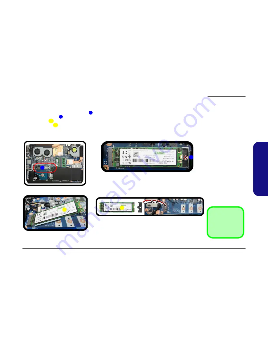
M.2 SSD-2 Removal Procedure

1.

Turn 

off

 the computer, remove the battery (

page 2 - 6

).

2.

Locate the module, it is visible at point 


(

Figure 13a

)

.

3.

Remove the screw 

 from the module 

(

Figure 13b

)

.

4.

The module 

 will pop-up

 (

Figure 13c

)

.

5.

Lift the module 

 up and off the computer

 (

Figure 13d

)

.

6.

Reverse the process to install a new module.

Figure 13

 M.2 SSD-2 Module 

Removal 


a. Locate the module.
b. Disconnect the cables and 

remove the screw.

c. The module will pop-up.
d. Lift the module up off  the 

socket.

1

2

3

3

a.

c.

1

2

3

b.

3

d.

3. M2 SATA Module

1  Screw

Содержание P705

Страница 1: ......

Страница 2: ...down properly and don t forget to save your work Remember to periodically save your data as data may be lost if the battery is depleted Do not expose the computer to any shock or vibration Do not plac...

Страница 3: ...pose If you do not have access to a compatible outlet have a qualified electrician install one When you want to unplug the power cord be sure to disconnect it by the plug head not by its wire Make sur...

Страница 4: ...r hands or metal objects Battery Guidelines The following can also apply to any backup batteries you may have If you do not use the battery for an extended period then remove the battery from the comp...

Страница 5: ...n jack on the left of the computer then plug the AC power cord into an outlet and connect the AC power cord to the AC DC adapter 6 Use one hand to raise the lid LCD to a comfortable viewing angle do n...

Страница 6: ...ed Dynamic Frequency Intel Dynamic Video Memory Technol ogy for up to 1 7GB Microsoft DirectX 11 1 Compatible Intel HD Graphics 4600 Core i7 4710HQ CPU Integrated Dynamic Frequency Intel Dynamic Video...

Страница 7: ...ts Slot 1 for Combo WLAN and Bluetooth Module Slot 2 for SATA or PCIe SSD Factory Option Slot 3 for SATA SSD Communication Built In Gigabit Ethernet LAN 2 0M FHD PC Camera Module WLAN Bluetooth M 2 Mo...

Страница 8: ...l Locator Top View with LCD Panel Open Figure 1 Top View 1 PC Camera 2 PC Camera LED When the PC camera is in use the LED will be illuminated in red 3 Built In Microphone 4 LCD 5 Power Button 6 Speake...

Страница 9: ...nal Locator Front Right Side Views Figure 2 Front View 1 LED Indicator Figure 3 Right Side View 1 S PDIF Out Jack 2 Microphone In Jack 3 Headphone Out Jack 4 USB 3 0 Ports 5 Multi in 1 Card Reader 6 R...

Страница 10: ...w 1 Introduction External Locator Left Side Rear View Figure 4 Left Side View 1 Vent 2 HDMI Out Port 3 Powered USB 3 0 Port 4 Mini DisplayPorts LEFT SIDE VIEW 1 2 3 4 Figure 5 Rear View 1 Vent 2 DC In...

Страница 11: ...ttom View 1 7 1 Introduction External Locator Bottom View Figure 6 Bottom View 1 Vent 2 Sub Woofer Overheating To prevent your com puter from overhea ting make sure no thing blocks any vent while the...

Страница 12: ...ing the connection make sure the connector is oriented in the same way The pin1 side is usually not indicated Pressure sockets for multi wire connectors To release this connector type grasp it at its...

Страница 13: ...pull on the wire 6 Peripherals Turn off and detach any peripherals 7 Beware of static discharge ICs such as the CPU and main support chips are vulnerable to static electricity Before handling any part...

Страница 14: ...ing collar socket by using a flat head screwdriver to pry the locking collar pins away from the base Figure 1b 5 Carefully lift the keyboard off the computer Figure 1c 1 2 3 4 5 6 7 7 8 6 a b 1 3 2 c...

Страница 15: ...in the direction of the arrow and remove it Figure 2b 4 The battery will be visible at point on the computer Figure 2c 6 1 2 19 20 21 22 Figure 2 Battery Removal a Remove the SD cover and screws b Rem...

Страница 16: ...ottom case starting from point as shown Figure 3f to avoid damaging the rear eSATA USB 3 0 port Tighten the screws to secure the bottom case in place 23 24 27 28 29 Figure 3 Battery Removal cont d d D...

Страница 17: ...er and remove the battery page 2 6 2 The HDD will be visible at point on the mainboard Figure 4a 3 Remove screws from the HDD assembly Figure 4b Figure 4 HDD Assembly Removal a Locate the HDD b Remove...

Страница 18: ...7mm h hard disk drive In some cases 9 5mm h hard disk drives will be installed It can be installed on either upper or lower slot There are two hard disk drive options Two changeable 2 5 6cm 7 0mm h S...

Страница 19: ...puter Memory 1 Upgrade Process 1 Turn off the computer turn it over remove the keyboard page 2 5 2 The RAM modules will be visible at point after removing the shielding plate Figure 6a 3 Remove screws...

Страница 20: ...slot 7 The module will only fit one way as defined by its pin alignment Make sure the module is seated as far into the slot as it will go DO NOT FORCE IT it should fit without much pressure 8 Press th...

Страница 21: ...y fit one way as defined by its pin alignment Make sure the module is seated as far into the slot as it will go DO NOT FORCE IT it should fit without much pressure 7 Press the module in and down towar...

Страница 22: ...omputer turn it over remove the battery page 2 6 2 The SSD module will be visible at point on the mainboard Figure 12a 3 Remove the screw Figure 12b 4 The SSD module Figure 12c will pop up and you can...

Страница 23: ...Figure 13a 3 Remove the screw from the module Figure 13b 4 The module will pop up Figure 13c 5 Lift the module up and off the computer Figure 13d 6 Reverse the process to install a new module Figure 1...

Страница 24: ...Insert the module in the computer Figure 14b 3 Tighten the screw to secure it in place Figure 14c 1 2 3 a 3 2 b c Top 1 Bottom Thermal Pad Be sure to place the thermal pad s adhesive side down onto t...

Страница 25: ...s shown Figure 15d 5 Make sure that the mylar is secure in place and the thermal pad is in place along the contour no glue is required 6 Replace the component bay cover and tighten the screws page 2 1...

Страница 26: ...ure 16a 3 Carefully disconnect the cables and then remove the screw Figure 16b 4 The Wireless LAN module Figure 16c will pop up and you can remove it from the computer 1 2 3 4 5 b c a 2 3 5 1 5 4 5 Wi...

Страница 27: ...es covers each cable will have either a black or transparent cable cover are color coded for iden tification as outlined in the table below Cable 1 is usually connected to antenna 1 Main on the module...

Страница 28: ...lly disconnect the cables and then remove the screw from the module Figure 17b 4 The module will pop up Figure 17c 5 Lift the module up and off the computer Figure 17d 6 Reverse the process to install...

Страница 29: ...a 3 Remove the screw from the module Figure 18b 4 The module will pop up Figure 18c 5 Lift the module up and off the computer Figure 18d 6 Reverse the process to install a new module Figure 18 M 2 SAT...

Отзывы: