
CV CHARTER
CV#
Description
Range
Default
CV1
Short address
1-127
3
CV2
Start voltage
0-32
10
CV3
Acceleration
0-32
0
CV4
Deceleration
0-32
0
CV5
Top voltage
0-32
32
CV29
Basic configuration
2
CV19
Advanced consist address
0-127
0
CV21 CV21=0, all accessory functions follow its own address. When CV21=1, all
functions will follow the consist address
CV49
odd number sound on, even number sound off 0-1
1
CV50
Horn type (34 types)
0-33
4
CV51
Horn volume
0-3
3
CV52
Bell type (8 types plus off, 8=off)
0-7
3
CV53
Bell volume
0-3
3
CV54
Bell ring rate
0-50
3
CV55
Diesel rumble volume
0-3
3
CV56
Brake squeal volume
0-3
3
CV57
Dynamic brake volume
0-3
3
CV58
Air release volume
0-3
3
CV59
Air pump volume
0-3
3
CV60
Safety pop valve volume
0-3
3
CV61
Engine cooling fan volume
0-3
3
CV62
Coupling volume
0-3
3
CV64
Rail wheel clack
0-3
3
CV65
Kick start voltage
0-63
63
CV67-94 28 speed steps table while CV29.4=1
1-255
CV112
Air compressor volume
0-3
3
CV113
Coupling fire volume
0-3
3
CV114
Brake release volume
0-3
3
CV115
Auto brake squeal enable/disable
0-1
1
CV117
light mode: 0=on/off, 1=on/off/dim, 2=rule17
0-2
0
CV122
Diesel notch mode, 0=auto notch 3=manual notch
0-3
0
CV123
Diesel prime mover select
0-2
0
CV125
Program to “1” will restore some CV’s to factory settings
0
FCC COMPLIANCE
This device complies with part 15 of the FCC Rules. Operation is subject to the following two
conditions. (1) This device may not cause harmful interference, and (2) This device must accept any
interference received, including interference that may cause undesired operation.
About US
XL Systems Inc has designed and manufactured model rail road products for MRC for more than 20
years. All MRC DCC products are made by XL Systems Inc. All our DCC products are compatible to
MRC DCC products. We will introduce more new products to meet customer’s beget. We also
provide installation and special programming and modification for customer. If you have special
needs please contact to us at: [email protected] or [email protected]. You also buy
directly from XL to get more saving.
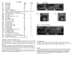
Completed installation
Fig 2
SPEED TABLE CV67-CV94 FOR 28 SPEED STEPS
When CV29’s bit 4 is set to “1” it will use the speed table formed by CV67-CV94 to control speed
(motor voltage). It allows you to setup each speed for all 28 speed steps. First, program CV29 to
18 for short addresses (1-127) or program CV29 to 50 for long addresses (128-9999) to enable
speed table control. Then select throttle to 28 speed steps and run your loco at speed step 1. Use
program
CV on the main to change CV67’s value (1-255) to adjust step 1’s speed. The kick voltage, CV65
is only applied when the speed step changes from 0 to 1. You should switch between 0 to 1
many times to check step 1’s speed. When done with CV67, select speed step 2 and program
CV68. CV68’s value must be greater then CV67’s. When done with CV67-CV94, use read back
CV to make sure their values are in increasing order.
Note: When using MRC Prodigy DCC to program addresses it will automatically disable the speed
table (set CV29’s bit 4 to “0”). Programming CV125 to 1 will also disable the speed table and re-
program CV67-CV94 to a default linear speed setting.
Fig 1
wrap tape
Fig 3
Fig 4


