XK-SAR : SAR90 / SAR360 Lighting System
SAR Bar Installation
Before installing the components on the vehicle, begin with a quick test off of the vehicle. Follow the wiring information on the next
page by first connecting all of the data input and data output wires between the SAR Controller and the SAR Bars. Then proceed by
connecting all RED power wires to positive voltage and the BLACK power wires to a ground. The vehicle’s battery will be sufficient
for this test. Power on and test functionality of the system. It is not necessary to set orientation at this point as they may be mixed up
when mounted on the vehicle.
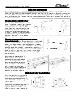
Mounting SAR Bars with L-brackets –
Included with each SAR Bar are two end-mount L-
brackets. Following the diagram to the right, loosely
mount the L-brackets to the ends of the light bar
with the lock washer between the bar and the
bracket. Place the light bar onto the vehicle in the
desired location. Mark the holes indicated by the
arrow and drill out the holes using a 3/8” drill bit.
Secure the brackets with the included hardware. To
finish the install, adjust light bar rotation to desired
position and then tighten the end cap hex cap
screws.
Mounting SAR Bars with Adjustable Rear Brackets
(SOLD SEPARATELY) –
This portion covers installation of the SAR Bars
with the optional Adjustable Rear Brackets. Begin first by mounting the
brackets to the desired location on the vehicle. Please note that the
MAX
spacing between these brackets will be 7 inches
LESS
than the length of
the bar (see arrow between brackets in diagram to the right). Example- on a
20 inch SAR Bar, the maximum distance these brackets can be apart is 13
inches. Measure, mark and drill a 3/8” hole for each bracket (downward
facing arrows to the right). Secure the brackets to the vehicle using the
supplied hardware.
Insert the supplied bolts into the rear of
the SAR Light bar. These will slide in on
the side nearest the orientation button as
shown in the first diagram to the right.
Insert the rubber spacers onto the bolts.
Position the light bar near the brackets,
insert the bolts into the brackets, and
secure with the included nuts and lock
washers. To adjust rotation or to move the
light bar from left to right, simply loosen
these nuts, reposition, and snug back.
SAR Controller Installation
Find a convenient location to mount the SAR
Controller. Using the provided 3M tape, firmly
press the controller into the location. Use the
center channel to feed the wiring through to the
rear if necessary.
Once mounted, use the two screws pointed out
in the second diagram to the right to adjust the
angle of the SAR Controller. When in place,
tighten the screws to lock the angle in place.


