


5
Connect the Cables
.
w
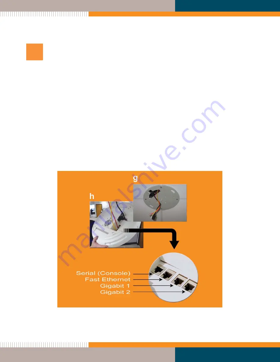
Feed the power and Ethernet cable(s) through the access hole in the ceiling tile and the
mounting plate, then connect the cables to the Array (steps g and h). The Ethernet
cable(s) should be connected as follows:
z
Gigabit 1 (mandatory)—used for the primary data and management connection
to the Array.
z
Gigabit 2 (optional)—used as a redundant connection to Gigabit 1.
z
Fast Ethernet (optional)—used for a management-only connection to the Array.
w
Turn ON the power switch.
w
Verify that the Ethernet link LED lights and the LED boot sequence begins—the IAP
LEDs on the front of the Array will illuminate in rotation.
Figure 4. Connecting the Cables
6


