background image


24 

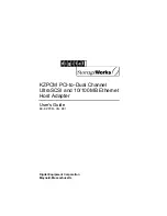
Z-BOX application in different mode: 

Working 

mode 

Switch setting 

Function 

ACT state from power on to 

succeed 

PC 

mode 


Coordinator 

ACT  flickers  1time/s 

  ACT 

always lights after networking 

succeed 


Router 

ACT  flickers 

3time/s 

  ACT 

always  lights  after  adding 

network succeed 

PLC 

mode 


Coordinator 

ACT  flickers 

1time/s 

  ACT 

always lights after networking 

succeed.  Then  ACT  flickers 

50time/s after 5s 

 read PLC 

BD  serial  port  station  no., 

ACT 

always 

lights 

after 

succeed. 


Router 

ACT  flickers  3time/s 

  ACT 

always  lights  after  adding 

network  succeed.  Then  ACT 

flickers  50time/s  after  5s 


read  PLC  BD  serial  port 

station no., ACT always lights 

after succeed. 


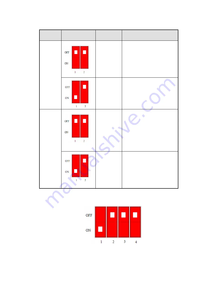
(4) Configure ZBOX-BD 

A

Turn on switch 1 of the 3 ZBOX-BD 


B

Install the 3 ZBOX-BDs on the 3 PLCs, power on them.   


Содержание Z-BOX

Страница 1: ...Z BOX wireless module User manual WUXI XINJE ELECTRIC CO LTD Data No ZC01 20110306 3 1 ...

Страница 2: ......

Страница 3: ...NJE ELECTRIC CO LTD Any copying transferring or any other usage is prohibited Otherwise Xinje will have the right to pursue legal responsibilities All rights including patent and permission of modules and designs are reserved January 2010 ...

Страница 4: ...OX 5 2 1 HARDWARE 5 2 2 SOFTWARE 8 3 ZBOX BD 9 3 1 HARDWARE 9 3 2 SOFTWARE 11 4 WIRELESS ANTENNA 14 4 1 TERMINAL ANTENNA 14 4 2 SUCKER ANTENNA 15 4 3 WALL MOUNTED ANTENNA 16 4 4 ANTENNA LAYOUT 17 5 APPLICATION 21 5 1 ONE HMI WITH MULTI PLC 21 5 2 DISTRIBUTED CONTROL SYSTEM 26 6 Q A 30 ...

Страница 5: ...oducts are new source for industry network which can simplify the network distribution save cost of network configuration and maintenance With the wireless network the product can remote monitor local device state collect technology parameters update terminal device program upload download recipe of local data ...

Страница 6: ...ller to realize wireless communication Refer to chapter 3 If the antenna of module and BD board is not long enough we provide below choices Name Function 2 4GHz terminal antenna Z BOX default configuration suitable for large and not complete closed space Refer to chapter 4 1 2 4GHz sucker antenna Suitable for narrow closed and strong signal shielded space such as metal electrical cabinet Refer to ...

Страница 7: ...er and repeater can extend the network Product features 1 Strong networking ability support star tree and mesh network ZBOX can auto select network structure as the actual environment 2 Network node has big capacity and fast starting speed the node quantity can up to 254 3 Use 2 4GHz wave band strong interference immunity ability 4 Lower power consumption 5 Easy to wiring network node can move and...

Страница 8: ... local devices upload download recipe data 4 Ensure the reliability and stability of communication Application 1 Industry control remote sensing remote measurement 2 Monitor the unattended machine room store house 3 Pipe network monitoring 4 Oilfield and coal data collection and monitoring 5 Factory remote distribution control ...

Страница 9: ...mit power 4 5dBm Working temperature 10 C 60 C Protocol Zigbee Modbus RTU Max data transfer speed 100Kb s Power supply ZBOX is active module It needs external power supply The power range is AC 85 264V 47 63Hz or DC 90 375V L N SWITCH There are 2 switches on the ZBOX Power supply Serial port SWITCH LED indicator ...

Страница 10: ... BOX power supply is normal when LED is ON COM Serial port Data exchange when LED is flickering RF Wireless signal The wireless signal send and receive when LED is flickering ACT Network Flicker 1 time s coordinator is building the network LED is always ON after networking is successful Flicker 3 time s router is adding the network LED is always ON after succeed Flicker 50 time s read the BD seria...

Страница 11: ...7 Serial port Z BOX module has a RS232 port which can connect PC HMI PLC and other devices DB 9 pin port 2 RXD 3 TXD 5 GND ...

Страница 12: ...C mode User can change the mode by ZBOX config software Z BOX Config software is used to change the working mode 1 Please download the ZBOX config software on www xinje com 2 Connect ZBOX and PC with TP cable power on the module 3 Open ZBOX config software Function 1 COM PC serial port 2 Device type config select PC mode or PLC mode 3 Unknown mode show the present module working mode 4 Read read t...

Страница 13: ...4GHz Max transmit power 4 5dBm 4 5dBm Working temperature 10 C 60 C 10 C 60 C Protocol Zigbee ModBus RTU Zigbee ModBus RTU Max transfer speed 100Kb s 100Kb s SWITCH There are 4 switches on the ZBOX BD No Description Function S1 Device type selection ON Router OFF Coordinator S2 State save selection ON Remember the network state recover the last network after re power on OFF Do not save the network...

Страница 14: ...s flickering ACT Network Flicker 1 time s coordinator is building the network LED is always ON after networking is successful Flicker 3 time s router is adding the network LED is always ON after succeed Flicker 50 time s read the BD serial port signal of PLC LED is always ON after succeed PLC mode RSII Signal weak signal medium signal strong signal ...

Страница 15: ...ve Software XCPpro software v3 1 and above Configuration steps 1 Install the ZBOX BD on the PLC or integrated PLC HMI controller 2 Connect the PLC or integrated PLC HMI controller with the PC open XCPpro software 3 Configure the COM3 parameter Click configure PLC comm port setting in the menu Click read from PLC in below window Then select serial port 3 and Modbus Num 1 Then click write to PLC Cli...

Страница 16: ...gram to the PLC At last re power on the PLC Download and upload program 1 Open the XCPpro software click Option comm Mode setting Input the PLC serial port 3 BD serial port station No in below window 2 Click configure BD setting Select BD serial port OK ...

Страница 17: ...13 3 Make the program and download to the PLC or upload from the PLC ...

Страница 18: ...nd not complete closed space Item Description Frequency 2400 2483MHZ Receiving sensitivity 106dBm Standing wave 1 8 Gain 3dBi Max transmit power 50W Input matched impedance 50Ω Interface SMA Male Communication distance Up to 150m open environment Antenna dimension Φ8 84 mm Note ZBOX default antenna is terminal antenna ...

Страница 19: ...ong signal shielded space such as metal electrical cabinet Item Description Frequency 2400 2483MHZ Receiving sensitivity 106dBm Standing wave 1 8 Gain 3dBi Max transmit power 50W Input matched impedance 50Ω Interface SMA Male Communication distance Up to 150m open environment ...

Страница 20: ...It is suitable for large area factory Item Description Frequency 2400 2483MHZ Receiving sensitivity 106dBm Standing wave 1 8 Gain 3dBi Max transmit power 50W Input matched impedance 50Ω Interface SMA Male Wall mounted antenna is mounted on the wall in order to expand the network cover area Please refer to below mounting steps ...

Страница 21: ...gle Put the antenna at suitable angle to cover the whole area 4 4 Antenna layout The antenna type is decided by actual environment and device distribution The following are some common mounting layout Environment Factory area is more than 2000 m2 Signal needs to pass through many walls Layout 1 Same floor same room ...

Страница 22: ...ers larger area than diagram 2 for the same device distribution on the same floor Although the diagram 2 can cover all the devices the signal is weak for the device far from the antenna Diagram 3 is suitable for the concentrated device distribution ...

Страница 23: ...factory which has office on the second floor Mount the antenna at the height of second floor to cover all the devices 3 Same floor different room Diagram 5 Diagram 6 Diagram 5 and 6 adopt different way for the same place Diagram 5 uses TBOX ZBOX and ZBOX BD Diagram 6 uses ZBOX ZBOX BD and repeater ...

Страница 24: ...20 4 Different floor The office and workshop is in the different floor There are up to two floors between the two antennas to ensure the normal communication ...

Страница 25: ...hree PLCs state via the simple SCADA in the control room 2 Device Item Quantity Function Xinje PLC 3 Terminal equipment Z BOX 1 Coordinator build the network XC ZBOX BD 3 Router add the network PC 1 To run the simple SCADA monitor the terminal equipment 3 Network ...

Страница 26: ...lick configure PLC comm port setting in the menu Click read from PLC in below window Then select serial port 3 and Modbus Num 1 Then click write to PLC Click BD in the left list Select BD serial port OK Then download empty program to the PLC At last re power on the PLC ...

Страница 27: ...um is 2 PLC slave 2 Modbus Num is 3 3 Configure the ZBOX module Connect ZBOX with PC set the switch as below Z BOX is the coordinator in PC mode If the signal is too weak the communication will not have packet error rate but delay If signal LED doesn t light please adjust the antenna position ...

Страница 28: ...LC mode Coordinator ACT flickers 1time s ACT always lights after networking succeed Then ACT flickers 50time s after 5s read PLC BD serial port station no ACT always lights after succeed Router ACT flickers 3time s ACT always lights after adding network succeed Then ACT flickers 50time s after 5s read PLC BD serial port station no ACT always lights after succeed 4 Configure ZBOX BD A Turn on switc...

Страница 29: ...25 5 Run the simple SCADA the screen is as the following Note the SCADA function please refer to TH series HMI manual ...

Страница 30: ...t and cost saving 1 Purpose Remote monitor the PLC state upload download program deal with the alarm and backup the data 2 Device Item Quantity Function Xinje PLC 6 Terminal device Z BOX module 6 Coordinator build the network XC ZBOX BD 6 Router add the network T BOX module 3 Transfer the data of ZBOX PC 4 Run SCADA to monitor the terminal device 3 Network ...

Страница 31: ...office 1 with PC set DIP switch as below working mode is PC 4 Configure ZBOX 2 Connect ZBOX2 of office 1 with TBOX set DIP switch as below working mode is PC 5 Configure ZBOX BD in workshop1 A set DIP switch of the 2 XC ZBOX BDs as below B Install the 2 XC ZBOX BDs on PLC1 and PLC2 power on the PLCs 6 Configure the TBOX in office1 Connect TBOX with PC open XCPpro software Click option Ethernet mod...

Страница 32: ...Note the details please refer to TBOX manual 7 Office1 SCADA screen The steps of workshop2 and 3 please refer to workshop1 The final SCADA is as below ...

Страница 33: ......

Страница 34: ...ode can add 6 sub nodes If sub node cannot be added the node depth is full The solution is re power on the node to lost the node information 2 the node is not in the network coverage area Please adjust the node position Q4 XC ZBOX BD XP3 ZBOX BD Z BOX PLC mode cannot read the station no A4 1 PLC serial port and BD are not configured Please refer to chapter 3 2 2 the serial port program of PLC has ...

Страница 35: ...WUXI XINJE ELECTRIC CO LTD 4th Floor Building 7th No 100 Dicui Rd Wuxi China Tel 86 0510 85134139 Fax 86 0510 85111290 www xinje com Email cheerfiona gmail com ...

Отзывы: