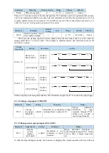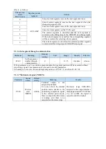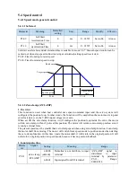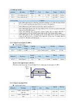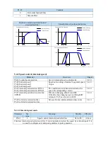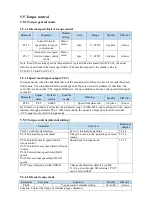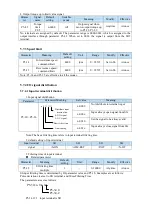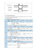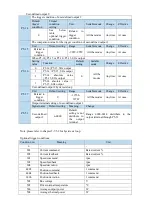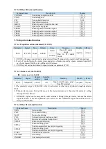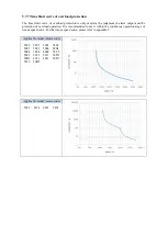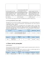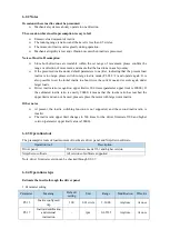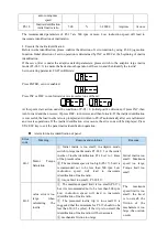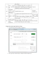
P5-34.2=3 basic filtering time is 3ms
P5-18=10 filtering time multiple is 10
So the total filtering time is P5-34.2 * P5-18=3ms*10=30ms
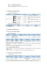
5.7.4.2 Output terminal distribution
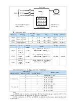
1. Output signal distribution
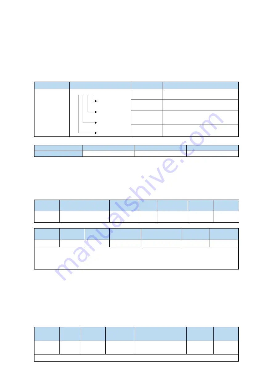
Parameter
Parameter Meaning
Set value
Meaning
P5-37
~
P5-53
n. 0
Distribute output
terminal no.
0: NO signal
1: NC signal
No meaning
No meaning
n.0000
Not distribute to terminal input
n.000x
Output always open signal from
SOx
n.0010
Set the signal to be always valid
n.001x
output always close signal from
SOx
2. Default setting of output terminal
Output terminal
SO1
SO2
SO3
Signal
/COIN
/ALM
/S-RDY
5.7.5 Output terminal function
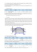
5.7.5.1 Servo ready output (/S-RDY)
Related parameter
Parameter
Meaning
Default
setting
Unit
Range
Modify
Effective
P5-70
/S-RDY: output
condition selection
1
-
0~1
Anytime
At once
Parameter
Signal
name
Default
setting
Suitable
mode
Meaning
Modify
Effective
P5-41
/S-RDY
n.0003
All
servo ready output
Anytime
At once
Refer to section 3.2.2 for hardware wiring details.
P5-41 parameter setting range is n.0000-0014, which is assigned to other output terminals through
parameters.
If it is necessary to output signal from SO2, P5-41 can be set to n.0002/0012.
Servo ready signal output conditions
When P5-70 is set to 0: after the driver initialization is completed and the servo has no alarm status
/S-RDY is valid;
When P5-70 is set to 1: after enabling, the servo has no alarm status /S-RDY is valid.
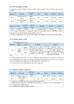
5.7.5.2 Rotating detection output (/TGON)
1. Signal setting
Parameter Signal
Default
setting
Suitable
mode
Meaning
Modify
effective
P5-40
/TGON
n.0000
All
Rotating detection
output
Anytime
At once
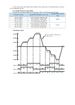
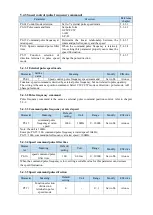
It is the output signal indicating that the servo motor is rotating at a speed higher than the set value.
Содержание DS5L1 Series
Страница 1: ...DS5L1 series servo driver User manual WUXI XINJE ELECTRIC CO LTD Data No SC5 05 20200929 1 0 ...
Страница 2: ......
Страница 6: ......
Страница 33: ...Voltage DC 30V maximum Current SO1 DC 500mA maximum 400W and below servo can support SO others DC 50mA maximum ...
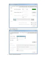
Страница 100: ...3 Set the auto tuning interface 4 Click ok to start inertia identification ...
Страница 106: ...3 set the auto tuning interface ...
Страница 112: ...with higher rigidity 6 Start auto tune 7 Open the servo enable then click ok ...
Страница 169: ...Appendix 9 Torque speed characteristic curve ...
Страница 170: ......

