background image


HDB-T3x0 Series, Quick Installation Guide 


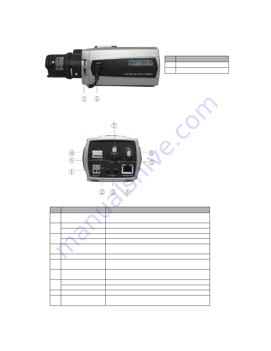
•    Front View 


NO 

Function 

Focus adjusting fixing screw


Auto IRIS lens connector


•    Rear View 


NO 

Function 

Description 

Power Adaptor Terminal

  Connects the supplied power adapter or an external 

power supply 12V DC or 24V AC, max. 4.0Watt. 

Power Indicator(Green) 

Indicates power input. 

Status Indicator(Red) 

Indicates camera status. 

Audio Input 

Audio Input Stereo Jack 

Audio Output 

Audio Output Stereo Jack 

Network Connector 
(PoE)


RJ-45 port compatible with 10/100Mbps, which have a PoE 
function.


Video Switch 

Selects Video On/Off. 

Set to On


to output a video signal. 

Video Output 

Connects the video output. This BNC connector 

provides a 1.0Vp-p/75 ohms composite video signal.


Micro SD Card Slot 

Card Slot for Micro SD. Open the protection cover 

with a supported tool to insert Micro SD card. 

3pin Terminal IO 

Connects alarm In/Out. 

2pin RS485 Terminal 

Connects PT device.


Reset Button 

Executes the factory default. 

11 

Video Output 

Connects the video output. This BNC connector 

provides a 1.0Vp-p/75 ohms composite video signal.


Содержание HDB-T3x0 Series

Страница 1: ...and makes it available on the network as real time full frame rate Motion JPEG and H 264 or MPEG 4 video streams The alarm input and alarm output can be used to connect various third party devices su...

Страница 2: ...Stereo Jack 4 Network Connector PoE RJ 45 port compatible with 10 100Mbps which have a PoE function 5 Video Switch Selects Video On Off Set to On to output a video signal 6 Video Output Connects the v...

Страница 3: ...can use external devices to signal the network camera to react on events Mechanical or electrical switches can be wired to the AI Alarm In and G Ground connectors G Ground Connect the ground side of t...

Страница 4: ...1 Connect the Network Camera device to the network and power up 2 Start SmartManager utility All programs NautilusClient16 SmartManager the main window will be displayed after a short while any networ...

Страница 5: ...Click Live View or Setup to enter web page 4 The encoder s Live View page appears in your browser 3 2 Access from the internet Access from the internet once connected the Network Camera is accessible...

Страница 6: ...4 1280x720 720x480 576 640x480 352x240 288 and 320x240 Users are allowed to select the most suitable one out of those modes Please adjust the mode in accordance with your PC specifications and monitor...

Страница 7: ...ther windows will be visible Press the Esc button on the computer keyboard to cancel full screen view The Manual Trigger button activates a pop up window to manually start or stop the event The Camera...

Страница 8: ...et the Network Camera to the original factory settings go to the Setup System Maintenance web page described in 3 5 6 System Maintenance of the User s Manual or use the control button on the network c...

Отзывы: